00191369-01.pdf - 第193页
User Manual HS-50 6 Vision functions Software-Version 5.01Edition 01/99 6.2 PCB vision system 191 )LGXFLDOVKDS H Always choose a well-s tructur ed, axial ly parall el, di stinct s hape as fi duci al sh ape: Recommen…
6 Vision functions User Manual HS-50
6.2 PCB vision system Software-Version 5.01 Edition 01/99
190
and coordinates of the fiducial are determined in each case by applying the correlation proce-
dure to the column and row profiles (see Fig. 6.2 - 2). From the coordinates obtained in this
way, the location, skew and shear of the board are determined.
Reject fiducials (= ink dots) are also detected and evaluated using the methods described
above.
&ULWHULDIRU&UHDWLQJ)LGXFLDOV
Basically the same criteria apply to both fiducials and reject fiducials (ink dots): uniqueness of fi-
ducial shapes and readily detectable structures which stand out from their surroundings.
8VHH[LVWLQJVWUXFWXUHVDVILGXFLDOV
Instead of fiducials, you can also use uniquely identifiable structures within the PCB layout. It
should, however, be remembered that solder stop lacquer is accompanied by a loss in contrast.
/RFDWLRQRIWKHILGXFLDOV
Position the fiducial where there are as few structures as possible and where the fiducial will stand
out well from its surroundings. Measuring outwards from the center of the fiducial, there should be
a clearance on each side equal to at least one fiducial size plus 1 mm.
7\SHVRIILGXFLDOV
There are 2 types of fiducials:
– Positive fiducials
The fiducial extends above the base material of the board.
– Negative fiducials
The fiducial is etched into the base material of the board.

User Manual HS-50 6 Vision functions
Software-Version 5.01Edition 01/99 6.2 PCB vision system
191
)LGXFLDOVKDSH
Always choose a well-structured, axially parallel, distinct shape as fiducial shape:
Recommended fiducial shapes:
5HFWDQJOHVTXDUHRUFLUFOH
Properties
– Low informational content (fiducials can easily be confused with test dots).
NOTE
Make sure that there are no similar structures in the fiducial search area.
– Low space requirements in the layout
– Very robust with respect to different tinning procedures (e.g. hot-tinning).
Recommended fiducial dimensions
– for square and rectangles: Side length 1.2 mm - 2.2 mm
– for the circle: Diameter 1.2 mm - 2.2 mm
'RXEOHFURVVDQGVLQJOHFURVV
Properties of the double cross
– Higher informational content
– More space required in the layout
– Sensitivity with respect to high tin-coatings (bare copper is preferable)
– Poor fiducial quality may result in incorrect position recognition.
Properties of the simple cross
– The informational content is somewhat lower than with the double cross
– Less space required in the layout than with the double cross.
– Less sensitive to high tin-coatings than with the double cross.
6 Vision functions User Manual HS-50
6.2 PCB vision system Software-Version 5.01 Edition 01/99
192
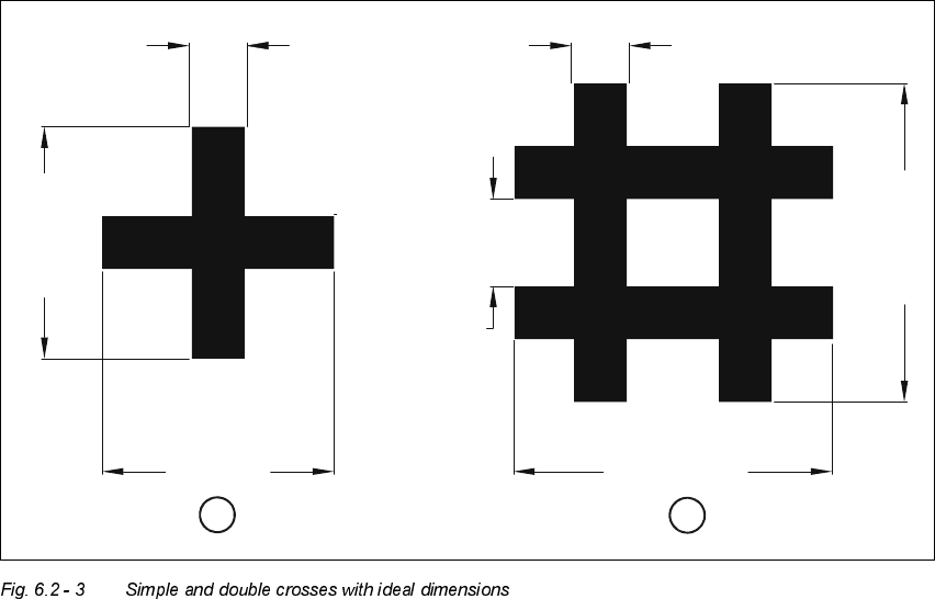
'LPHQVLRQVRIWKHILGXFLDOV6LPSOHDQGGRXEOHFURVVHV
.H\WR)LJ
(1) Simple cross
(2) Double cross
The minimum dimensions for a fiducial in length (l) and width (b) depend on the line thickness (s)
and on the structure of the fiducial.
– Length (l) and width (b)
For the good fiducial recognition, the length and the width should be at least 0.9 mm with the
simple cross and 1.8 mm with the double cross. The ideal dimensions for the simple cross are
2.0 mm and for the double cross 2.75 mm. Under normal circumstances, length and width will
be equal.
– Line thickness (s)
The ideal line thickness for both fiducial types is 0.5 mm. The line thickness may vary, however,
according to standard structure widths and the type of fiducial. You should ensure that the line
is at least 0.3 mm thick, though.
– Line spacing (a)
Line spacing depends on the type of fiducial. Under no circumstances should line spacing fall
below 0.5 mm. For the double cross, the ideal spacing will be 0.75 mm.
l = 2.75 mm
l = 2.0 mm
b = 2.0 mm
s = 0.5 mm s = 0.5 mm
b = 2.75 mm
a = 0.75 mm
2
1