00191369-01.pdf - 第200页
6 Vision functions User Manual HS-50 6.3 Component Vision System Software-Version 5.01 Edition 01/99 198 .H\WR)LJ (1) Axi s of symme try &ULWHU LDIRUL UUHJXODU FRPSRQHQWV Definition : A compone nt i…
User Manual HS-50 6 Vision functions
Software-Version 5.01Edition 01/99 6.3 Component Vision System
197
cess yield information on positional deviations, lead condition and component identification. The
HALE process has proved to be highly resistant to interference factors such as unwanted reflec-
tions, diffused light influences , etc. and it is faster and more accurate than the matching method.
Once measurement has been completed, the star advances to station 9 where the segment ro-
tates the component into the correct orientation for placement. Finally, in star station 1, the com-
ponent is placed in its correct position on the board.
&ULWHULDIRU5HFRJQLWLRQRI&RPSRQHQWV
6KDSHRIWKH&RPSRQHQWV
Optical component centering allows both regular and irregular components to be centered. The
maximum number of leads, horizontally and vertically, is 99 in each case.
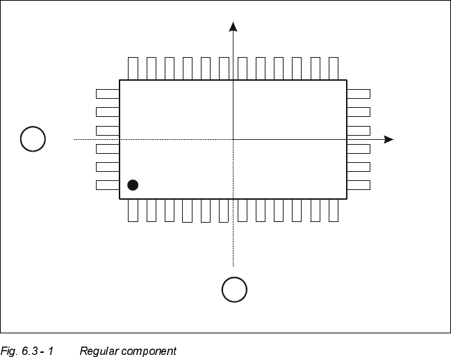
&ULWHULDIRUUHJXODUFRPSRQHQWV
Definition:
A component is deemed to be regular when it satisfies the following four conditions:
– rectangular package shapes (special case: square shape)
– only one lead type per side
– only one lead group per side
– opposite lead groups located symmetrically with respect to the two main axes
(x and y axes).
Y
X
Pin 1
1
1
6 Vision functions User Manual HS-50
6.3 Component Vision System Software-Version 5.01 Edition 01/99
198
.H\WR)LJ
(1) Axis of symmetry
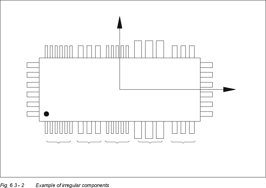
&ULWHULDIRULUUHJXODUFRPSRQHQWV
Definition:
A component is deemed to be irregular when it does not satisfy the conditions for regular compo-
nents.
Additional conditions for centering with the component vision system:
– In any one row up to 3 different lead types are permitted.
– In any one row up to 15 groups are permitted.
3LWFKGHYLDWLRQ
The pitch deviation (which is the distance from the center of one lead to the center of the next) can
be edited separately for each component in the GF editor. If this value is exceeded during the vi-
sion inspection, the component will not be centered and therefore not placed.
X
Pin 1
Y
X
Pin 1
Type 1
Group 1
Type 2
Group 1
Type 1
Group 2
Type 3
Group 1
Type 2
Group 2
User Manual HS-50 6 Vision functions
Software-Version 5.01Edition 01/99 6.4 Access to the ’Teach Fiducial’ and ’Test Component’ Options
199
/LPLWYDOXHVIRUTXDOLW\P HDVXUHPHQW
Components exceeding the limit values for quality measurement will be rejected and, therefore,
not placed:
– Difference in the number of leads between the original and the model.
– Pitch deviation larger than the value in the GF file.
– Larger orthogonality error than specified in the GF file.
– Larger deviations of the external dimensions.
– Deviation of the central point greater than the permitted positional tolerance for pick-up.
$FFHVVWRWKH¶7HDFK)LGXFLDO¶DQG¶7HVW&RPSR
QHQW¶2SWLRQV
Access to the ’Teach fiducial’ and ’Test component’ options is only available to user class Line en-
gineer and higher. The ’Teach fiducial’ and ’Test component’ icons will remain grayed out until user
classes ’Line engineer’ or ’Service engineer’ have been selected. The grayed-out icons will be ac-
tivated and appear black, indicating that the options are available.
6HOHFWLRQRIXVHUFODVVHV
Å In the menu bar of the 0DLQYLHZmenu click on the 2SWLRQVpull-down menu.
Å Click on the $FFHVVOHYHOoption. The user class option box will drop down.
Å Select the appropriate user class.