00191369-01.pdf - 第22页
1 Introduction User Manual HS-50 1.4 Revision index Software Version 5.01 01/99 Issue 20 6HUYLFH HQJLQHHUV This clas s is res erved f or Sieme ns engin eers, who are tra ined to ca rry out s ervicing work and to upgra…
User Manual HS-50 1 Introduction
Software Version 5.01 01/99 Issue 1.3 User classification
19
&RPSRQHQWKDQGOLQJ
In this chapter you will find information concerning the feeder modules and the components
they can be used to insert.
6WDWLRQH[WHQVLRQVRSWLRQV
Overviews of the nozzle changers, PCB barcode readers, Remote Service, etc.
6RIWZDUHLQVWDOODWLRQ
This chapter tells you how to install the software.
1R]]OHRYHUYLHZ
This chapter is made up of the nozzle contour diagrams and nozzle overviews. The nozzle
contour diagrams are used to determine the placement shadow for the individual nozzles.
8VHUFODVV LILFDWLRQ
The operating software is structured so that certain functions or menus can only by used or
called by appropriately trained personnel. There are three different classes of user:
– operators,
– line engineers and
– service engineers.
Access to each class may be password-protected. Chapters containing information for user
classes higher than "operator" contain a reference to the user class concerned in the footer.
2SHUDWRUV
The operator class consists of any person who has been trained in operation of the machine.
These people are authorized to use any functions associated with operating the machine and
may call up any menus needed to use the machine.
/LQHHQJLQHHUV
Line engineers have undergone special training and are authorized to carry out line engineer
activities, such as creating set-up configurations, determining vision parameters, etc.

1 Introduction User Manual HS-50
1.4 Revision index Software Version 5.01 01/99 Issue
20
6HUYLFHHQJLQHHUV
This class is reserved for Siemens engineers, who are trained to carry out servicing work and
to upgrade and retrofit the placement system.
WARNING A thorough knowledge of the relevant part of this User Manual is
required before carrying out any work on the machine. All work must be carried out by appro-
priately trained and qualified personnel. All warning, caution and danger notes MUST be ob-
served.
PLEASE NOTE: The content of this User Manual is not part of or intended to modify a previous
or existing agreement, undertaking or legal relationship. Any undertakings entered into by Si-
emens AG result from the purchase contract, which also contains complete and generally ap-
plicable guarantees. Such contractual guarantee provisions are neither extended nor
restricted by the information given in this User Manual.
5HYLVLRQLQGH[
0DQXDO 6RIWZDUHYHUVLRQ ,VVXH
First draft HS-50 Provisional User Manual 5.01 09/98
Revision of HS-50 User Manual 5.01 01/99
User Manual HS-50 1 Introduction
Software Version 5.01 01/99 Issue 1.5 Description of the machine
21
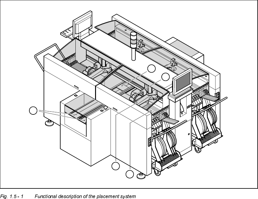
'HV FULSWLRQRIWKHPDFKLQH
)XQFWLRQDOGHVFULSWLRQ
The automatic placement system is a high-performance placement system with four gantry
axis systems. A PCB vision system and a star-shaped 12-segment revolver head are mounted
on each gantry. Revolver placement heads equipped with a component vision system pick up
the components from stationary feeder modules and insert them into the PCB clamped in the
PCB conveyor.
1. 12-segment revolver placement head with component vision camera
2. Gantry axis system with PCB vision camera
3. Stationary component feeder
4. Clamped PCB
5. PCB conveyor (dual conveyor option)
3
5
2
4
1