00191369-01.pdf - 第233页
User Manual HS-50 6 Vision functions Software-Version 5.01Edition 01/99 6.5 Teach Fiducial 231 The resul ts of fiduci al cente ring ar e indica ted by a c ross. The x and y offset values o f the fid ucial center w ill be…
6 Vision functions User Manual HS-50
6.5 Teach Fiducial Software-Version 5.01 Edition 01/99
230
If you have selected a fiducial the fiducial number and the fiducial name will appear in the display
field.
&HQWHU2SWLRQ
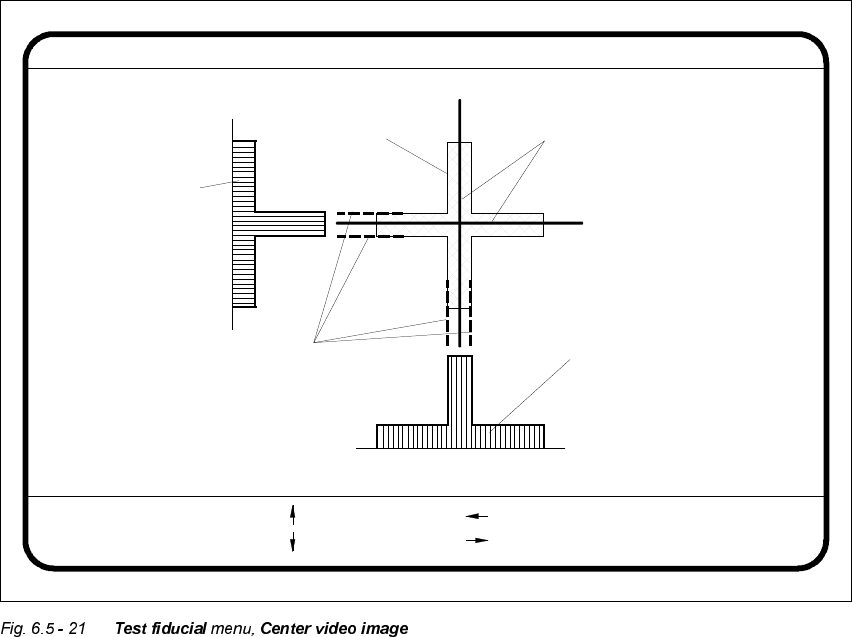
If you click on the &H QWHU button the 7HVW ILGXFLDO menu will close and the video image is shown
on the screen. The picture shows the 2D fiducial structure and the rows and columns profiles of
the 1D structure used for determining precisely the center of the fiducial. Header and footer will
be shown as well.
The &H QWHU function determines via software the center of the fiducial. The parameters for the
function, the edges of the fiducial structure, are selected via a dialog. The system draws edge line
markings as suggestions at possible edge positions.
Å With the arrow keys shift the current edge line marking designated in the header.
Å With 5HWXUQ you can accept the position of the suggested edge line marking or the one whose
position you changed. The system will then show you the next edge line marking. The se-
quence in which testing takes place is ’Fiducial edge left’, ’Fiducial edge right’, ’Fiducial edge
top’, and lastly, ’Fiducial edge bottom’. This notation appears in the header.
Edge ok
Fiducial No. = 8 Edge = left
Ret :
Center fiducial
: up
: dn
: right
: left
Fiducial
Result: Centering crosshair
Edge line markings to be shifted
via cursor keys
Row profile of fiducial
Column profile
of fiducial
User Manual HS-50 6 Vision functions
Software-Version 5.01Edition 01/99 6.5 Teach Fiducial
231
The results of fiducial centering are indicated by a cross. The x and y offset values of the fiducial
center will be entered in the fiducial data field.
PLEASE NOTE
An incorrectly centered fiducial will cause a placement offset.
Å Press the (VF key to quit the option and return to the 7HVWILGXFLDO menu.
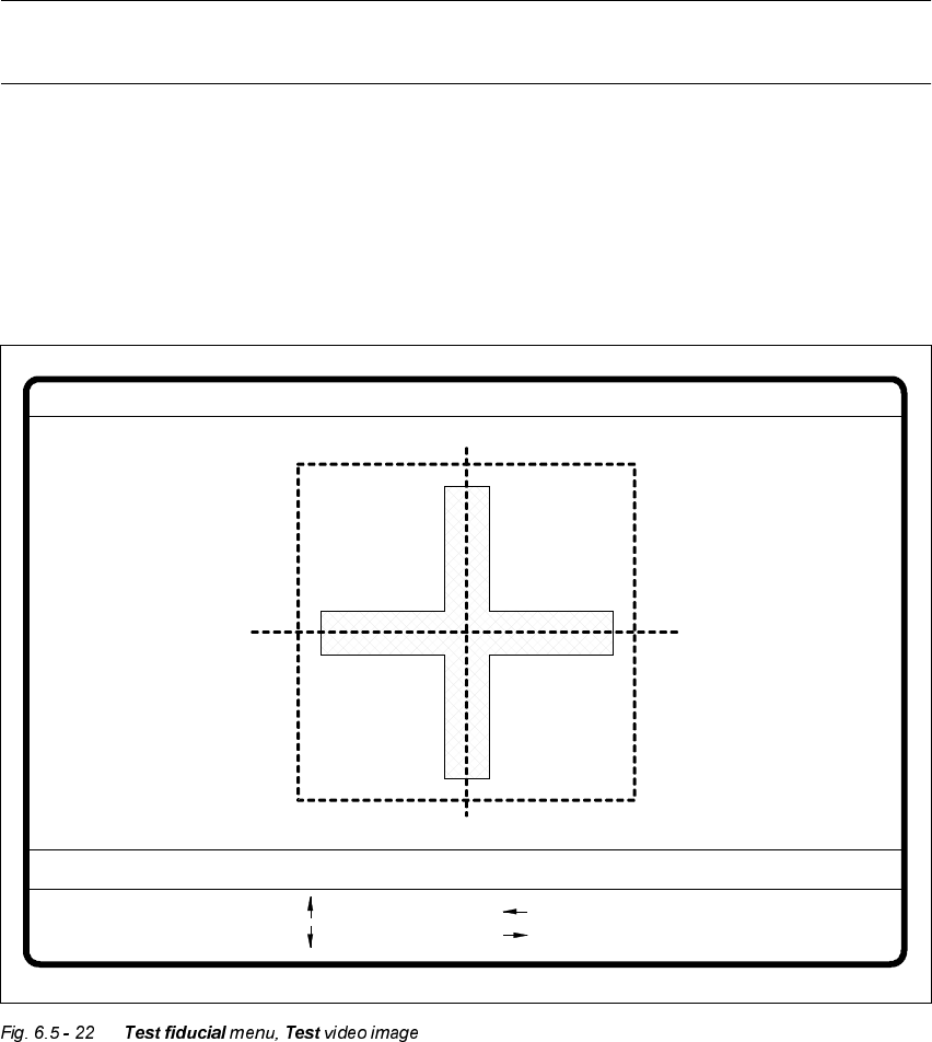
7HVW2SWLRQ
If you click on the 7HVWbutton the 7HVWILGXFLDO menu will close and the video image be displayed
on the screen.
The dimensions of the pattern structure and search area are stored in the station computer. These
figures are required for calculating the travel path for the corners test. The centering offsets of any
fiducial centering which may already have been carried out will also be taken into account in cal-
culating the travel path.
Fiducial No. = 8 Quality fact. = 70Test fiducial
test
1..6 : x/y step
Ret :
x/y step width = ...
: x axis +
: x axis -
: y axis +
: y axis -
6 Vision functions User Manual HS-50
6.5 Teach Fiducial Software-Version 5.01 Edition 01/99
232
Following this
– the test will be shown on the video display as it runs,
– the header will be shown with the option, the fiducial number and the quality factor, and
– in the footer the operator fields and command sequences will be shown and a test started
which determines the fiducial’s quality factor.
Å By pressing the 5HWXUQ key you can repeat the test procedure.
Å You can change the position of the gantry with the arrow keys. By entering the numbers 1 - 6
you can change the step width.
The PCB camera travels into the 4 corners of the search area, and each time, issues a measure-
ment command. For each measurement command, the machine controller is provided with the fi-
ducial quality by the vision analysis unit (MVS). The worst value (which is the worst case) of the
test is displayed on the screen in the header.
The quality value is a figure between 0 (= bad) and 100 (= very good) and should not fall below
the value 40 for the fiducial and the ink dot. If it does, we recommend you choose another fidu-
cial.
0RYH;<$[HV2SWLRQ
When you select this option from the 7HVWILGXFLDO menu, the station computer will have the fol-
lowing actions carried out:
– The screen will close the 7HVWILGXFLDO menu and will switch over to the video image. At the
same time the current camera position will be displayed and the operator field option dropped
down.
– If there is the risk of a gantry/head crash, the axis controllers will be blocked.