00191369-01.pdf - 第259页
User Manual HS-50 6 Vision functions Software-Version 5.01Edition 01/99 6.6 Test Component 257 0HDVXUH&RPSRQHQW2SWLRQ NOTE This option can only be activate d if you ha ve alrea dy loaded a package form n …
6 Vision functions User Manual HS-50
6.6 Test Component Software-Version 5.01 Edition 01/99
256
Å With the 5HWXUQ key you can call all defined individual steps in the measurement procedure
one after the other. Each time you press the 5HWXUQ key a measurement command is given
and the results shown on the screen.
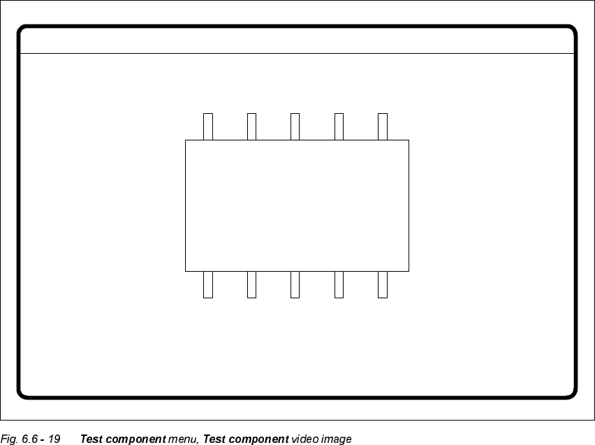
Å Use (VFto quit the option. The video image closes and the 7 H VW FRPSRQHQW menu reappears.
GF No. = 5Display component
User Manual HS-50 6 Vision functions
Software-Version 5.01Edition 01/99 6.6 Test Component
257
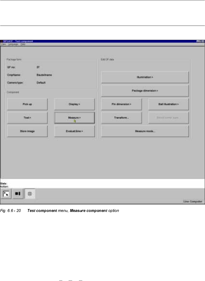
0HDVXUH&RPSRQHQW2SWLRQ
NOTE
This option can only be activated if you have already loaded a package form number and a com-
ponent has been picked up.
When this option is activated the following actions are started:
– The video image appears on the screen.
– The measurement command is given, using the predefined parameters.
– The MVS performs each component-specific measurement step in turn.
– The measurement values are displayed in the video image.
In addition to conventional components with lead connections, the 80F
4
or 80F
5
machines can
also optically center BGAs (B
all Grid Arrays) and flip-chips. The body of BGA and flip-chip com-
ponents is made of passivated silicon chips. Such bodies have strong reflective properties and
6 Vision functions User Manual HS-50
6.6 Test Component Software-Version 5.01 Edition 01/99
258
their surfaces are wavy. The connections of these components take the form of balls with a diam-
eter of at least 80 µm. Ball-grid arrays have their connections, as the name suggests, arranged in
the form of a grid - this means that they can be described in terms of rows and columns.
With flip-chips the balls are arranged irregularly over the body of the component body. The coor-
dinates of each connection will therefore need to be ascertained individually.
The Pick & place head of the 80F
4
or 80F
5
machines pick up the BGAs or flip-chips from flatpack
magazines. However the analysis procedures used currently for conventional components are no
longer adequate for the optical centering of BGAs or flip-chips. For this reason new analysis meth-
ods and new lighting techniques have been developed for the Pick & place sensor and FC sensor
in order that this new generation of components can be centered. BGAs and flip-chips which can-
not be centered optically will be returned to the flatpack magazines by the Pick & place head.
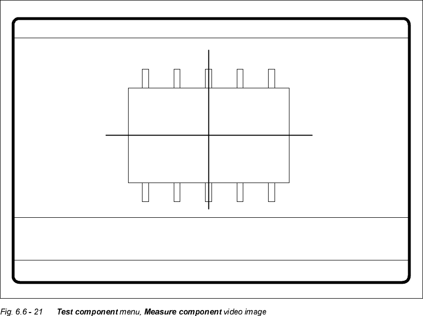
Measure component GF No. = 5
X offset = ... Y offset = ... Phi = ...
Orthogon = ...
No. of pins = ...
Quality fact. = ...
Length[mm] = ...
Width[mm] = ...
Spacing[mm] =
RET: Measure component
P.dev.[mm] =