00191369-01.pdf - 第268页
6 Vision functions User Manual HS-50 6.6 Test Component Software-Version 5.01 Edition 01/99 266 Procedu re: All of the ball s define d in the packag e form file ar e survey ed. Geometr ic crit eria are used here in the…
User Manual HS-50 6 Vision functions
Software-Version 5.01Edition 01/99 6.6 Test Component
265
– From these data the rough position and the skew of the component are determined. The mea-
sured position of the component is marked with white crosshairs.
Rectangle:
dark blue: 4 search windows, depending on the pattern tolerances and
the number of balls
Cross:
white: Ball model candidates found
Overlays:
white: Balls found which are defined in the package form file
Crosshairs:
white: Results of position recognition -> x and y angles
Star:
white: Center of the component ->Position
Synthetic model representation at the lefthand edge of the video image:
Image: Model in pixel resolution
Points marked with red plus signs (+):
outside the circle:
Contrast < 0, ball is darker than the background
within the circle:
Contrast > 0, ball is lighter than the background
Points marked with yellow minus signs (-):
The difference between the plus and minus signs represents
the radial tolerance.
%DOOGULY HQPRGH
See Section 6.6.4.14 on page 6 - 281 for a definition of the measuring methods.
The method works with high precision and is thus suitable for precisely determining the position
of all defined balls. As a higher precision search, ball-driven mode will follow grid-driven mode.
This measurement method can be identified
– by the synthetic model being shown in pixel resolution at the lefthand edge of the video image,
– by there being a window around every ball (separate window) or
– by a window covering the entire component or over a defined row of balls (combined window)
- this will depend on the memory.
6 Vision functions User Manual HS-50
6.6 Test Component Software-Version 5.01 Edition 01/99
266
Procedure:
All of the balls defined in the package form file are surveyed. Geometric criteria are used here in
the selection of the window mode:
– If the separation of two balls is low (< 2 ball diameters) the FRPELQHGwindow mode will be
preferred.
– If the balls are relatively far apart the VHS DUD WH window mode will be selected. The default win-
dow mode is the VHSD UDWHwindow mode.
Window:
dark blue: Over a single ball in each case (separate window)
Over a row or over all balls (combined window)
Cross:
white: Measured ball candidates which are defined in the package form file.
Crosshairs:
white: Results of position recognition -> x and y angles
Star:
white: Position of the component
Synthetic ball model representation
in pixel resolution on the lefthand edge of the video image
A description will be found in the *ULGGULYHQPRGHsection.
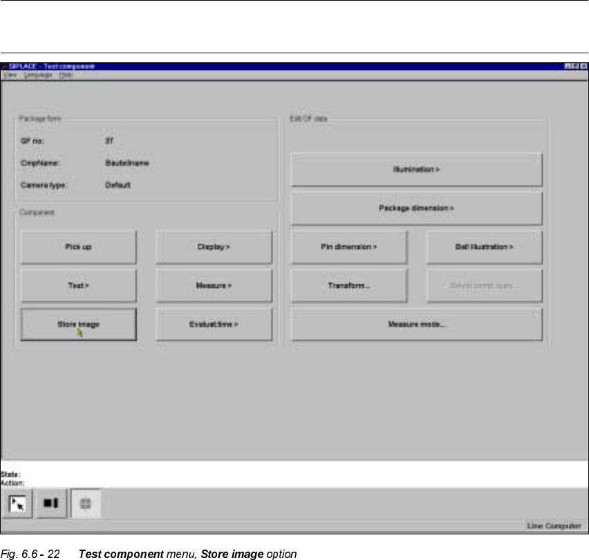
User Manual HS-50 6 Vision functions
Software-Version 5.01Edition 01/99 6.6 Test Component
267
6 WRUHLPDJH2 S WLRQ
NOTE
You cannot click on this option until a package form number has been loaded.
This menu is used to store the generated video image as a file on the hard disk of the machine
controller. The file name and path are preset to:
C:\TMP\MVSBILD.MVS
For further analysis at Siemens AG, copy the file from the hard disk of the MVS controller onto a
diskette and send it to the PL EA Service Department.