00191369-01.pdf - 第287页
User Manual HS-50 6 Vision functions Software-Version 5.01Edition 01/99 6.6 Test Component 285 – TWI N method ( T wo Wi ndows) T wo win dow s are se lecte d. This met hod is particula rly su itable for r apid a nalysi s,…

6 Vision functions User Manual HS-50
6.6 Test Component Software-Version 5.01 Edition 01/99
284
– vary the integration settings.
5HVROXWLRQIRUWKHDQJOHFDOFXODWLRQ
In this measuring mode, if the component rotation has been calculated incorrectly on account of
ambiguity, you can increase the angular resolution in order to determine the angle of rotation. The
following increments may be used in relation to the resolution in order to determine the angle of
the components:
– Low resolution:
– Medium resolution
Determining the angle every 4° within the angular tolerance
– High resolution
Determining the angle every 2° within the angular tolerance
– Very high resolution
Determining the angle every 1° within the angular tolerance
0HWKRGIRUFDOFXODWLQJWKHURWDWLRQ
Here you must specify the number of rotation windows in order to determine the angle:
– Automatic selection
The system selects the number of windows.
– SWIN method (Single Window)
Selects a single window. This method is suitable for small components and fluctuating dimen-
sions.
$ QJXODUWROHUDQFH
Determining the
angle for the
following
angles
- Angular tolerance
2
- 15° - 33°
0° - 8° - 18°
+Angular tolerance
2
0° - 8°
8° 0°
15° 8°
18°
33°
Tab. 6.6.2
User Manual HS-50 6 Vision functions
Software-Version 5.01Edition 01/99 6.6 Test Component
285
– TWIN method (Two Windows)
Two windows are selected. This method is particularly suitable for rapid analysis, for PLCCs,
for example. However, this requires the structures to be investigated to lie in the center of the
window. If this is not the case, select just one window (SWIN method).
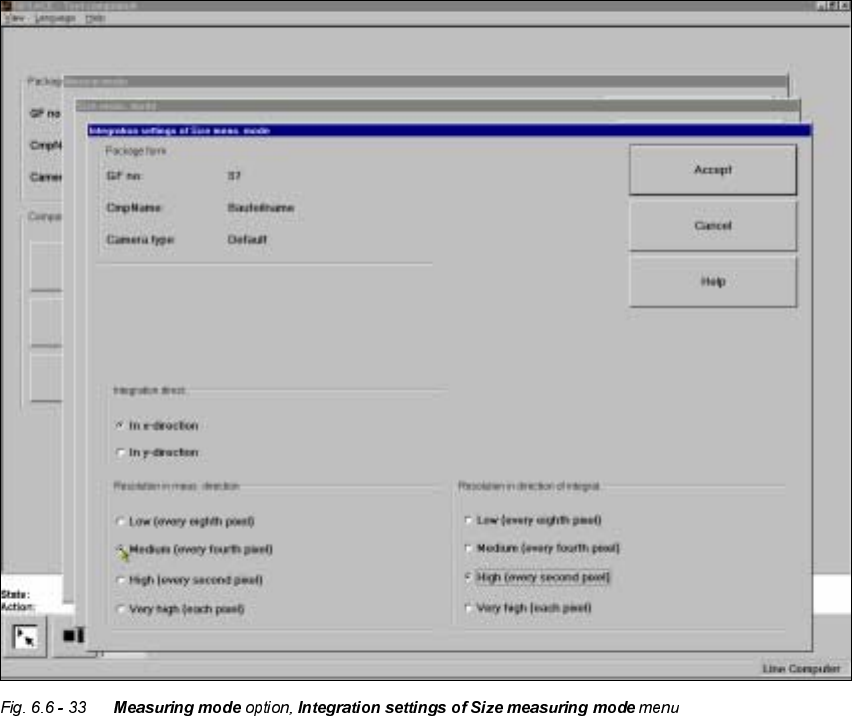
,QWHJUDWLRQVHWWLQJV
If you click on the 'Integration settings' field, the ,QWHJUDWLRQVHWWLQJVRI6L]HPHDVXULQJPRGH
menu will appear on screen.
This menu is used to select the
– integration direction,
– the resolution in the measuring direction and
– the resolution in the integration direction.
,QWHJUDWLRQGL UHF WL RQ
6 Vision functions User Manual HS-50
6.6 Test Component Software-Version 5.01 Edition 01/99
286
In order to determine the angle, select the integration direction towards either the X or Y axis of
the component. We recommend that you select the longer edge.
5HVROXWLRQLQWKHPHDVXULQJGLUHFWLRQ
Select this resolution in order to optimize the measuring times at the revolver head.
5HVROXWLRQLQWKHLQWHJUDWLRQGLUHFWLRQ
Select this resolution in order to optimize the measuring times at the revolver head.
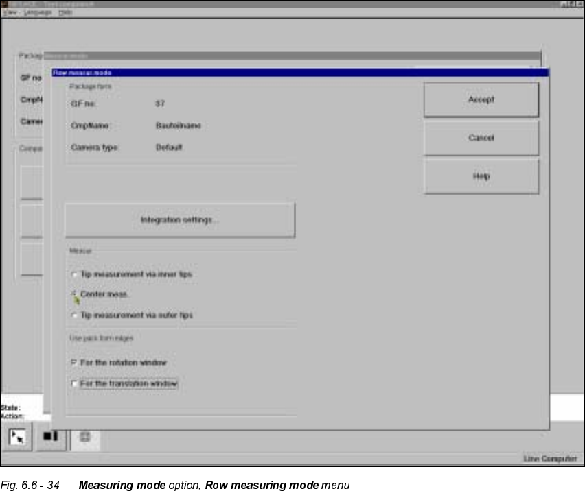
5RZ0HDVXULQJPRGH
Click on the ‘Setting’ field in the 5RZPHDVXULQJPRGH menu to call up the following menu:
This menu is used to
– specify the lead measuring method.
– use the package form edges for the rotation windows and/or translation windows.