00191369-01.pdf - 第296页
6 Vision functions User Manual HS-50 6.7 Guidelines for Describing Package Forms Software-Version 5.01 Edition 01/99 294 $Q DO \V LV This is us ed to analyz e the posit ion of the balls and to determine whether they ar…
User Manual HS-50 6 Vision functions
Software-Version 5.01Edition 01/99 6.6 Test Component
293
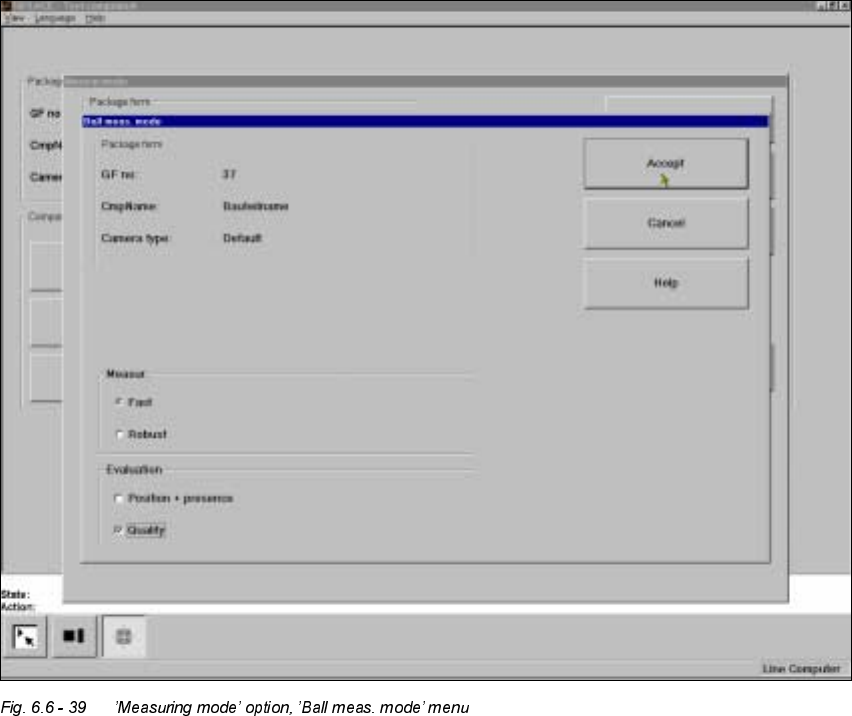
¶%DOO¶ P HDVXULQJPRGH
Click on the ’Settings’ button in ’Ball’ measuring mode to call up the ’Ball measuring mode’ menu.
This menu can be used to
– select the measuring methods listed under ’Measurement’ and
– evaluate the position and presence of balls and carry out a quality analysis.
0HDVXUHPHQW
You can choose between the following measuring methods:
– the profile method for fast analysis or
– the filter method for a more robust measuring method, although this will take longer.
The ’fast’ measuring method is generally sufficient. However, we recommend the ’robust’ measur-
ing method if the quality is insufficient, for example if the quality factor is less than 50.
6 Vision functions User Manual HS-50
6.7 Guidelines for Describing Package Forms Software-Version 5.01 Edition 01/99
294
$QDO\VLV
This is used to analyze the position of the balls and to determine whether they are present. It can
also be used to determine the quality of the measurement. The quality of the measurement should
generally be better than 50.
If you are placing flip-chips with high reproducibility, i.e. if there is very little difference between the
optical parameters of the flip-chips, we recommend the following settings to guarantee fast place-
ment:
– Switch off the determination of position / presence for components with large balls and spacing.
The position of the components has already been adequately determined using the grid mea-
surement of 3 balls per corner, and the ball presence analysis is unnecessary.
– Do not activate determination of the quality of the measurement unless you want to detect han-
dling or production errors.
Determination of the position is always necessary if the individual ball positions differ greatly from
the grid structure, i.e. if the individual ball positions are fairly scattered about the desired position.
*XLGHOLQHVIRU'HVFULELQJ3DFNDJH)RUPV
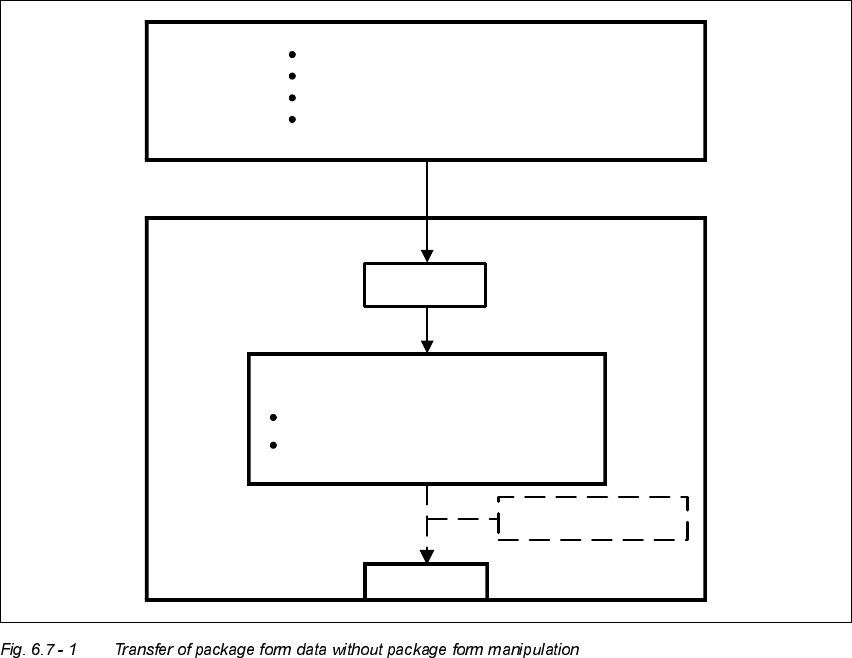
7UDQVIHURI3DFNDJH)RUP'DWDDQGWKH3DFNDJH)RUP,QWHUSUHWHU
If a package form is transferred to the station without an .SST file, the package form interpreter
will make certain settings to enable the package form to be measured in accordance with the pack-
age form description.
User Manual HS-50 6 Vision functions
Software-Version 5.01Edition 01/99 6.7 Guidelines for Describing Package Forms
295
In SIPLACE automatic placement machines, the package form interpreter is located in the ma-
chine controller. The communication module transfers the signals for controlling the lighting from
the MC to the cameras.
7DVNVRIWKH3DFNDJH)RUP,QWHUSUHWHU
– Automatic selection of suitable measuring modes
– Automatic selection of the measuring parameters
– Automatic differentiation between cubic/not cubic
– Automatic setting of the lighting
The package form interpreter processes standard components and automatically identifies spe-
cial components. Under certain circumstances, other components have to be post-processed. If
the package form settings have to be manipulated, these changes will be stored in the .SST file
and transferred back to the line computer.
LC
Package form library
Describe package for & components
Assign nozzles
Select cameras
.OGF
Package form interpreter
SC
MVS
Automatic selection of meas. modes
Automatic lighting selection
Hard disk
GF manipulator