00191369-01.pdf - 第306页
6 Vision functions User Manual HS-50 6.7 Guidelines for Describing Package Forms Software-Version 5.01 Edition 01/99 304 6HWWLQJWKH&RPSRQHQWV, OOXPLQDWLRQDWWKH[5H Y ROY HU+HDG&DPHUD *H…
User Manual HS-50 6 Vision functions
Software-Version 5.01Edition 01/99 6.7 Guidelines for Describing Package Forms
303
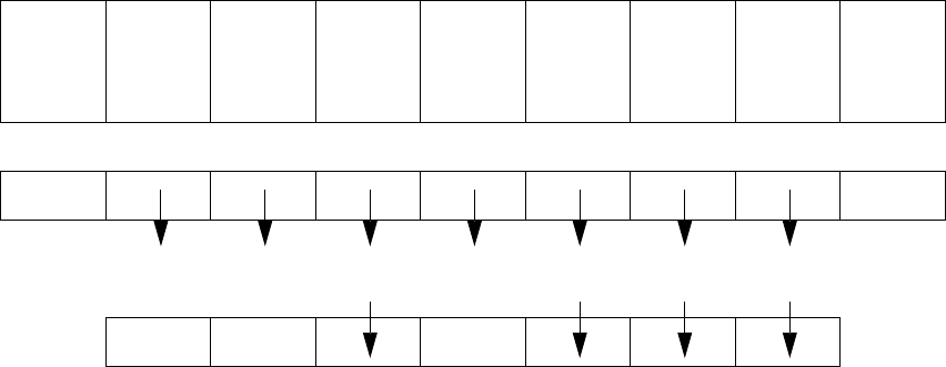
3DUDPHWHUVIRUWKH0HDVXULQJ0HWKRGV
Possible sequences of measuring methods
It is also possible to program other sequences, such as corner followed by lead or lead only. Such
combinations are very unusual, however. If the component is defined in the package form editor,
then the measuring methods will be pre-assigned. However, in some cases it may be necessary
to modify the measuring methods at the station so that the component can also be optically cen-
tered.
The results from the last measurement are always saved. The previous measurement is used as
a rough centering step for the next measurement and thus helps to reduce the measuring window.
The more measuring methods are used, the longer the entire measuring procedure will be. A large
number of measuring methods for a component can delay the head cycle. This applies to the re-
volver head in SIPLACE automatic placement machines, in particular.
PDC/
FDC
FDC FDC FDC FDC FDC
Flip-
chips
HS50/
S20/F
Ball
grid ar-
ray
Bare
dies
Size Size Size Size Row Row Size Size Size
Lead Corner Corner Corner Corner Grid Grid
6 Vision functions User Manual HS-50
6.7 Guidelines for Describing Package Forms Software-Version 5.01 Edition 01/99
304
6HWWLQJWKH&RPSRQHQWV,OOXPLQDWLRQDWWKH[5HYROYHU+HDG&DPHUD
*HQHUDO,QIRUPDWLRQRQ,OOXPLQDWLRQ0HWKRGV
The idea of illumination setting is to obtain an image of the leads of a component which is as high-
contrast as possible. At the same time it is also important to suppress representation of the body
of the component.
These instructions are intended to help you find the best possible illumination parameters. This,
however, does not imply that you rigidly comply with the values specified in these instructions. The
way you should proceed is first to follow these instructions and then to adjust the parameters your-
self where necessary. It may well be that you come across a component where the leads are better
illuminated using values different than the ones suggested in these instructions.
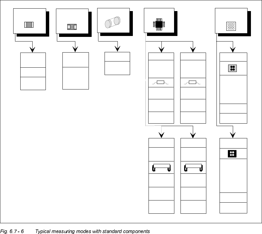
Flip Chip
Chip
General
SIZE
high
resolution
0402,
0603, etc.
SIZE
LEAD
outer tip
LEAD
outer tip
SIZE
Tantalum
capacitor
Melf IC
BGA, µBGA
Flipchip
SOJ,
PLCC
Small
SIZE
CORNER
outer tip
LEAD
outer tip
LEAD
outer tip
CORNER
outer tip
ROW
outer tip
SO,
QFP
Large
Small Large
BGA
GRID
BALL
PLCC
SIZE
CORNER
Beinmitte
CORNER
lead center
LEAD
lead center
ROW
lead center
LEAD
lead center
GRID
BALL
SIZE
(depend-
ing on
component
size)
SIZE
(depend.on
component
size)

User Manual HS-50 6 Vision functions
Software-Version 5.01Edition 01/99 6.7 Guidelines for Describing Package Forms
305
The illumination system consists of three different illumination levels. The intensities can be pro-
grammed individually. By using the individual illumination levels one at a time or in combination,
you can adapt the illumination to suit a wide range of components.
)ODWLOOXPLQDWLRQOHYHO
The flat illumination level is used for illuminating BGAs, µBGAs, flip-chips, J-lead components
(PLCC), Melfs and components with convex-type leads. It tends to emphasize body and lead
edges. It is, however, less suitable for displaying bright component bodies and ceramic compo-
nents.
0LGGOHLOOXPLQDWLRQOHY HO
The middle illumination level can be used universally with a wide range of components. With bright
component bodies, ceramic components, µBGAs and flip-chips it should, however, only be used
at lower intensity levels.
6WHHSLOOXPLQDWLRQOHYHO
The main application for the steep illumination level is for reflective leads, ceramic components
and bright component bodies. It is less suitable for reflective component bodies, flip-chips or
µBGAs.
NOTE
Most components will require a combination of these three illumination levels to achieve optimum
illumination. Using RQH illumination level will only be successful in exceptional cases.