00191369-01.pdf - 第31页
User Manual HS-50 1 Introduction Software Version 5.01 01/99 Issue 1.10 Setting up the placement system 29 6HWWLQJXSWKHSODFHPHQWV\VWH P 7 UD QVSRUWGL PHQVLRQV The place ment sys tem mou nting kit ( A) on…
1 Introduction User Manual HS-50
1.9 Dimensions and weight of the placement system Software Version 5.01 01/99 Issue
28
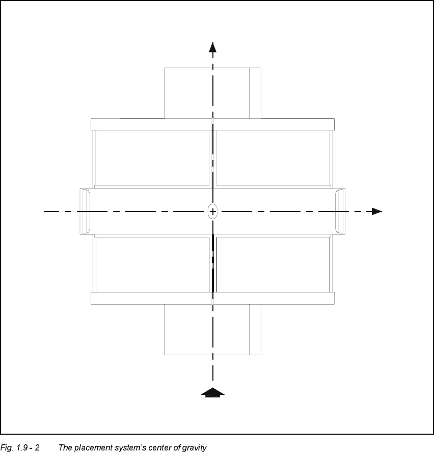
7KHSODFHPHQWV\ V WH P¶VF HQWHURIJUDYLW\
X coordinate 0 mm
Y coordinate 0 mm
Z coordinate 350 mm high
T PCB transport direction
These center of gravity coordinates relate to placement systems with a PCB transport height
of 830 mm.
X
Y
T
(0, 0, 350)
User Manual HS-50 1 Introduction
Software Version 5.01 01/99 Issue 1.10 Setting up the placement system
29
6HWWLQJXSWKHSODFHPHQWV\VWH P
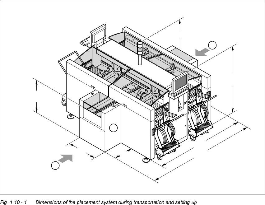
7UD QVSRUWGLPHQVLRQV
The placement system mounting kit (A) on the input side can be dismantled for transportation
purposes, which will reduce the width of the machine from 2380 mm to 1960 mm.
A Mounting kit which can be dismantled for transportation purposes.
B Points for attaching the fork-lift truck (fork length 2500 mm)
The PCB conveyor height is 830 mm ± 15 mm (or 952.5 mm ± 15 mm in accordance with the
SMEMA standard). The height specifications for the machine will change accordingly.
420
1790 (1912,5 SMEMA)
1592
(1714,5 SMEMA)
1960
2380
800
A
B
B
830±15
(952,5 ± 15 SMEMA)
1 Introduction User Manual HS-50
1.10 Setting up the placement system Software Version 5.01 01/99 Issue
30
7UDQVSRUWFRQILJXUDWLRQDQGWUD QV SRUWDWLRQ
The following components are not installed when the placement system is delivered from the
factory:
– keyboards
– monitors
– fault indicator lamps and
– component tables
Å Install the dismantled components for commissioning.
Å Use a fork-lift truck to transport the placement system:
– minimum fork length 2000 mm if the mounting kit is dismantled.
– minimum fork length 2500 mm if the mounting kit is still fitted.
Å Attach the fork-lift truck only at the indicated points.
4XDOLW\RIWKHIRXQGDWLRQ
Å Ensure that
– you set up the placement system on a firm and non-vibrating foundation.
– the load bearing capacity per unit area of the foundation is greater than 1000 kg/m².
&RPSUHVVHGDLUVXSSO\
– The pressure of the compressed air supply must be 5.5 bar ± 0.5 bar.
– The compressed air must conform to the above specification.
This can be achieved with
– oil-free compressors, e.g. Atlas, Copco type ZR4
– compressed air washer/driers
– micro-filters, series X, e.g. from Zander
3RZHUVXSSO\
– The power socket must be fused with the following fuse ratings:
3 x 16 A for 3 x 400 VAC
3x32A for 3x204VAC
3x16A for 3x460VAC