00191369-01.pdf - 第312页
6 Vision functions User Manual HS-50 6.8 Recommendation for vis ually centering components Software-Version 5.01 Edition 01/99 310 – Mea sure the co mponen t. Measur ement is succes sful . – Res et the s ettings t o the …
User Manual HS-50 6 Vision functions
Software-Version 5.01Edition 01/99 6.7 Guidelines for Describing Package Forms
309
7HVWLQJ,OOXPLQDWLRQ6 HWW LQJV
You can set the illumination parameters by calling the ’Illumination’ option (see Section 6.6.4.8 on
page 6 - 272). Using the ’Measure Component Option’ on page 6 - 257 you can then measure the
component and check your settings with the aid of the measurement results.
Proceed as follows to test your illumination setting:
Å Using the illumination values suggested in Figures 6.7 - 7 or 6.7 - 8 carry out measurement.
Measurement should run through successfully.
Å For each level reduce the set brightness level by 50 %.
Measurement should run through successfully.
Å For each level raise the set brightness level by 50 %.
Measurement should run through successfully.
If you are not successful with the above procedure, proceed as follows:
Å Starting with the suggested illumination value, increase the brightness of each individual illu-
mination level for as long as measurement is still successful.
Å Find this upper limit value for each individual illumination level in turn.
Å Starting with the suggested illumination value, decrease the brightness of each individual illu-
mination level for as long as measurement is still successful. Find this lower limit value for each
individual illumination level in turn.
Å Determine the average value of the upper and lower limit values. This will be the optimum illu-
mination value.
([DPSOHRIDQLOOXPLQDWLRQWHVW
– Settings from the diagram:
flat: 170
middle: 60
steep: 120
– Measure the component. Measurement is successful.
– Reduce setting values by 50%.
flat: 85
middle: 30
steep: 60
– Increase setting values by 50%.
flat: 255
middle: 90
steep: 180

6 Vision functions User Manual HS-50
6.8 Recommendation for visually centering components Software-Version 5.01 Edition 01/99
310
– Measure the component. Measurement is successful.
– Reset the settings to the suggested values:
flat: 170
middle: 60
steep: 120
© optimum setting
NOTE
With respect to 0402 and 0603 components, avoid the nozzle being displayed during imaging. If
this seems likely, remove the component from the nozzle and use the ’Illumination Option’ (see
page 6 - 272 to see whether the nozzle did appear in the image.
*HQHUDO,QIRUPDWLRQRQ6HWWLQJ,OOXPLQDWLRQ9DOXHV
– As a rule it is better to overilluminate the component than to underilluminate it. A saturated im-
age is preferable to a low-contrast image.
– Optimum illumination is attained when only the leads are imaged and the component body is
not shown.
– If you cannot clearly separate the image of the component body from the leads, we recom-
mend to illuminate body and leads equally and then to measure the outline.
5HFRPPHQGDWLRQIRUY LVXDOO\FHQWHULQJFRPSR
QHQWV
9LVXDOO\FHQWHULQJIOLSFKLSV
(QWHULQJWKHGDWDRQWKHOLQHFRPSXWHU
Å Describe the ball radius.
Å Select tolerances of between 10 % and 20 %.
6HWWLQJWKHSDUDPHWHUVRQWKHVWDWLRQFRPSXWHU
Å Under the’ Illumination Option’ in the ’Test Component Menu’, select the flat illumination plane
and set the brightness values to between 200 and 255. Do 127 use transformation tables to
do this.
User Manual HS-50 6 Vision functions
Software-Version 5.01Edition 01/99 6.8 Recommendation for visually centering components
311
Å Select a positive ball contrast under the Ball Image Option (see page 6 - 276).
PLEASE NOTE
If a lot of ’non-ball structures’ are identified as ball structures (they can be recognized by the
small crosses), increase the ball contrast. The number of crosses can be estimated in the
’Measure’ menu during the grid measurement.
5HFRPPHQGHGVHTXHQFHRIPHDVXUHPHQWVIRUIOLSFKLSV
5HFRPPHQGHGVHTXHQFHRIPHDVXUHPHQWVIRUYLVXDOO\FHQWHULQJIOLSFKLSV
*HQHUDOUHFRPPHQGDWLRQVIRUFHQWHULQJIOLSFKLSV%*$VDQGVFUHHQLQJ
SODWHV
6HWWLQJWKHEDOOFRQWUDVWSDUDPHWHUV
If you select a high value for the ’Ball image’ option in the ’Test component’ menu, this will reduce
the effect of any defective structures. It does mean, however, that there is a possibility that not
every ball will be detected.
Set a lower value to ensure that all the balls are detected. This will reduce the reject rate, but the
measurement will take longer.
6HWWLQJWKHEDOOUDGLXVSDUDPHWHUV
Enter the ball radius on the line computer. This value is automatically reduced by 20 % since the
vision system will detect balls even if the specified dimensions are smaller then their actual phys-
ical dimensions.
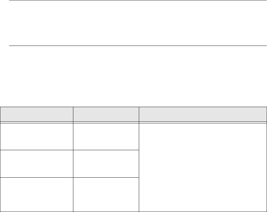
6L]HPHDVXULQJPRGH *ULGPHDVXULQJPRGH %DOOPHDVXULQJPRGH
Resolution for calculating
the angle:
low resolution
For single measure-
ment:
3 balls per corner
Standard
ball detection:
Hex value P1 = 80
Fast
ball detection:
Hex value P1 = A0
PLEASE NOTE:
Switch Ball mode off if it is not necessary
to measure all the balls.
In this case, P1 must be set to 80 in Grid mode.
Resolution in the measur-
ing direction:
medium
For multiple measure-
ment:
5 balls per corner
Resolution
in the integration direction:
medium
Hex value P1 = 80
Tab. 6.8.1