00191369-01.pdf - 第333页
User’s Manual SIPLACE HS-50 7 What schould you do ... Software Version S R.501.xx Edition 01/99 7.7 Changing the set-up 331 'LVFRQQHFWLQJWK HFRPSRQHQW W DEOH Å Click o n the symbol (S t op proce ssi…
7 What schould you do ... User’s Manual SIPLACE HS-50
7.7 Changing the set-up Software Version SR.501.xx Edition 01/99
330
.H\WR)LJ
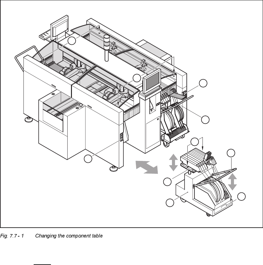
7.7 - 1
(1) Button for raising and lowering the component tabletop
(2) Socket for connecting the power supply cable
(3) Component tabletop (can be raised and lowered)
(4) Component table
(5) Bracket
(6) Tape waste container
(7) Centered bore hole for the centering pin
(8) Gap between the component table and machine stand
6
5
4
3
2
1
7
2
1
8
User’s Manual SIPLACE HS-50 7 What schould you do ...
Software Version SR.501.xx Edition 01/99 7.7 Changing the set-up
331
'LVFRQQHFWLQJWK HFRPSRQHQW WDEOH
Å Click on the symbol(Stop processing PCB) in the main view of the station computer
user interface. The station will continue to place components until the current PCBs are com-
pletely populated and have been transported to the intermediate or output conveyor, i.e. until
the processing conveyors are empty.
Å Click in the tool bar in the main view on the symbol for the gantry that you want to move out of
the feeder area using the gantry functions.
Å Click in the "Gantry functions" view on the 0RYHWR VHWXSSRVLWLRQ button and press the start
key as often as you are requested to do so.
The gantry moves from the feeder area to the set-up position.
Å Open the protective cover of the selected gantry.
Å Push the bracket of the component table upwards (see Fig. 7.7 - 1, No. 5).
This places the raised component tabletop in its end position.
Å Open the cover over the button used to raise and lower the component tabletop (see
Fig. 7.7 - 1
, No. 1).
Å Press the button and hold it down until the component tabletop (see Fig. 7.7 - 1, No. 3) is in its
upper end position.
The component tabletop latches into the raised position when the button is released.
Å Unplug the power supply cable of the component table from the socket on the station (see Fig.
7.7 - 1
, No. 2).
Å Pull out the component table.
7 What schould you do ... User’s Manual SIPLACE HS-50
7.8 How to avoid track errors Software Version SR.501.xx Edition 01/99
332
+RZ WRDYRLGWUDFNHUURUV
*HQHUDOLQIRUPDWLRQ
Å Make sure that the areas around the feeder modules are clean and that there are no loose
components in the feeder area or under the feeder modules.
Å Ensure that the supporting surfaces of the feeder modules, and particularly the magnetic rails
of the component tables, are clean and level.
Å Refill promptly with components.
Å Splice the tapes promptly. This generally means that you are to prepare the splicing material
when there is still approximately 1.5 m of tape on the reel.
Å Handle the feeder modules carefully when you insert them into or remove them from the com-
ponent table as these are high-precision devices.
Å When you insert the feeder modules, make sure that you do not accidentally press one of the
program keys. If you do, you could change the advance from 4 mm to 2 mm on
8 mm S feeder modules, for example.
Å Close the flaps of the feeder modules because they can be easily damaged when open.
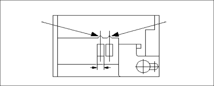
Å For 8 mm S feeder modules, make sure that the components are picked up from the correct
position, depending on their sizes (see the following example).
Example for 8mm S feeder modules
Å Check to see if all the plugs of the feeder modules are plugged in to the correct sockets.
Pick-up position
Pick-up position
> 3 mm
for components
< 3 mm
for components
Width