00191369-01.pdf - 第42页
1 Introduction User Manual HS-50 1.12 Overview of the modules - gant ries Software Version 5.01 01/99 I ssue 40 The y axis essent ially cons ists of the following main modu les: – y ax is linea r drive wi th perma nent…
User Manual HS-50 1 Introduction
Software Version 5.01 01/99 Issue 1.12 Overview of the modules - gantries
39
7HFKQLFDOGDWDIRUWKH[D[LV
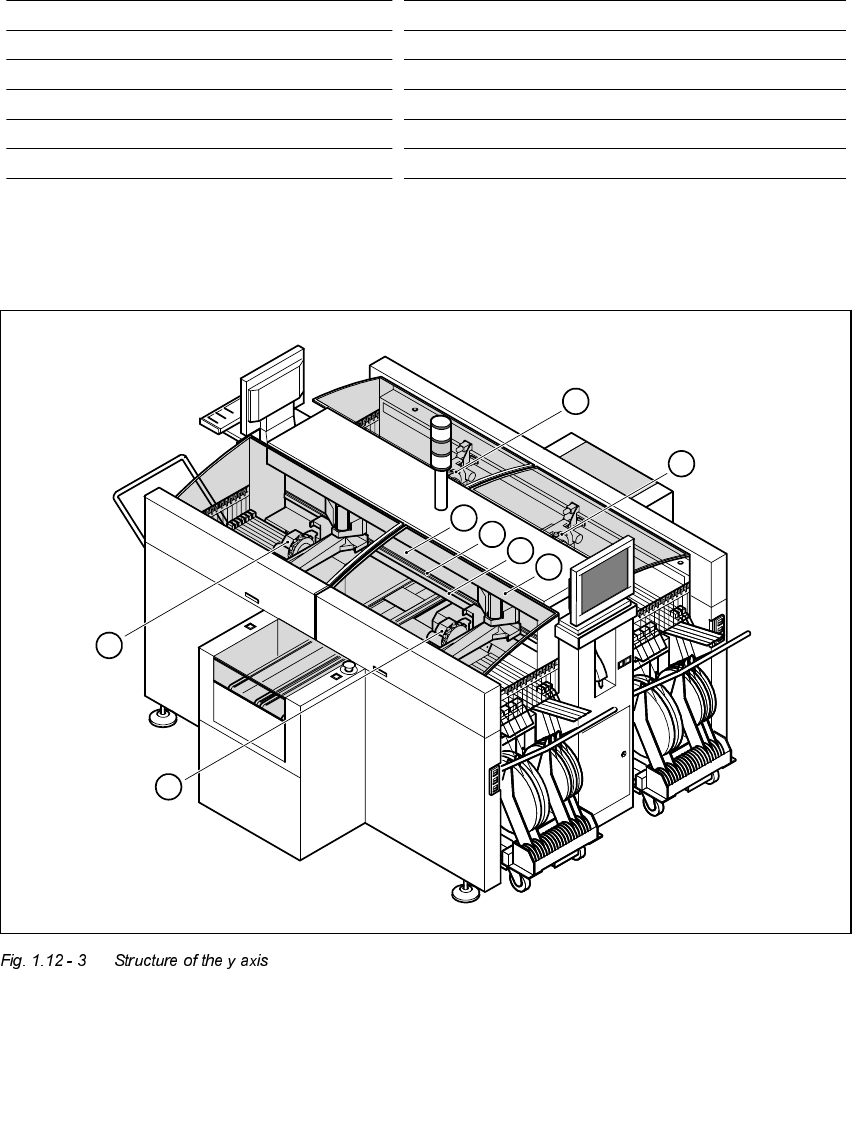
6WUXFWXUHRIWKH\D[LV
Drive Three-phase AC servomotor/toothed belt
Maximum speed 2.5 m/sec.
Traversing path 375 mm
Distance measuring system Metal linear scale
Measured length 400 mm
Scale length 420 mm
Resolution 1 µm
1. Gantry 1 5. Permanent magnet
2. Gantry 2 6. Guide system
3. Gantry 3 7. Measuring system
4. Gantry 4 8. Adapter plate
4
1
2
3
5
6
7
8

1 Introduction User Manual HS-50
1.12 Overview of the modules - gantries Software Version 5.01 01/99 Issue
40
The y axis essentially consists of the following main modules:
– y axis linear drive with permanent magnet (1) and adapter plate (2)
– y axis guide system
– y axis measuring system
The y axis is driven by a linear motor. The secondary part of the drive is made up of permanent
magnets and is mounted on the machine frame. The primary part is bolted to the gantry
(adapter plate). An anti-crash circuit prevents the traversing paths of the gantries meeting.
7HFKQLFDOGDWDIRUWKH\D[LV
Drive Direct, linear motor
Maximum speed 2.5 m/sec.
Traversing path of the gantries. calculated from Gantry 1 - 688.5 mm
the center of the machine: Gantry 2 - 768.5 mm
Gantry 3 - 688.5 mm
Gantry 4 - 768.5 mm
Distance measuring system Metal linear scale
Scale length 1530 mm
Resolution 1 µm
User Manual HS-50 1 Introduction
Software Version 5.01 01/99 Issue 1.13 Overview of the modules - revolver head
41
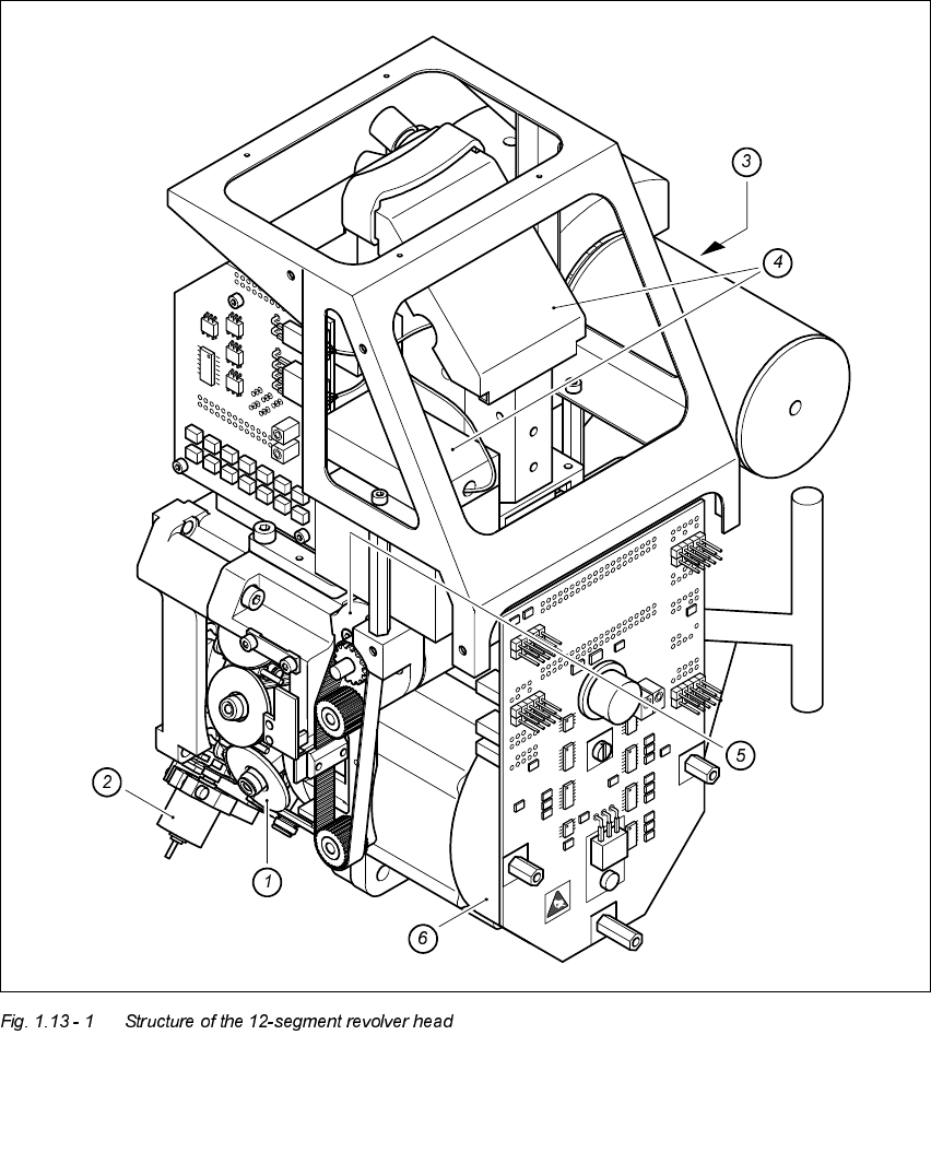
2YHUYLHZRIWKHPRGXOHVUHYROYHUKHDG
6WUXFWXUHRIWKHVHJPHQWUHYROYHUKH DG
1. Star with 12 sleeves 4. Component vision system
2. Motor for "Reject" valve adjustment drive 5. Z axis drive
3. Turning station 6. Star motor