00191369-01.pdf - 第46页
1 Introduction User Manual HS-50 1.14 Overview of the modules - vision systems Software Version 5.01 01/99 Issue 44 7 HFKQLFDOGDW D3&%YLVLRQV\ V WH P Fidu cials Up to 3 per placem ent program Local fi du…

User Manual HS-50 1 Introduction
Software Version 5.01 01/99 Issue 1.14 Overview of the modules - vision systems
43
2YHUYLHZRIWKHPRGXOHVYLVLRQV\V WHPV
Each placement system has
– four component vision cameras on the placement heads and
– four PCB vision cameras on the underside of the x axis gantries.
The vision evaluation units are located in the control unit for the placement system and the
component vision system is used to determine:
– the precise position of the components at the nozzle and
– the geometry of the package form.
The PCB vision system uses fiducials on the PCBs to determine:
– the position of the PCB,
– its rotation angle
– and the PCB delay.
The PCB vision system also uses fiducials on the feeder modules to determine the exact pick-
up position of components, which is particularly important for small components.
7HFKQLFDOGDWDFRPSRQHQWYLVLRQPRGXOHRQWKHVHJPHQWUHYROYHU
KHDG
Maximum component dimensions 18.7 mm x 18.7 mm
Range of components 0402 to PLCC44
including BGA, µBGA, flip-chip, TSOP, QFP
PLCC, SO to SO32, DRAM
Lead spacing > = 0.5 mm
Field of vision 24 mm x 24 mm
Illumination method Front-lighting (3 levels programmable as required)

1 Introduction User Manual HS-50
1.14 Overview of the modules - vision systems Software Version 5.01 01/99 Issue
44
7HFKQLFDOGDWD3&%YLVLRQV\ V WH P
Fiducials Up to 3 per placement program
Local fiducials Up to 2 per component (may be of different types)
Library size Up to 255 fiducial types
Image processing Gray scale-based correlation
Illumination method Front-lighting
Recognition time per fiducial/ink spot 0.4 s
Field of vision 5.7 mm x 5.7 mm
User Manual HS-50 1 Introduction
Software Version 5.01 01/99 Issue 1.15 Overview of the modules - PCB conveyor
45
2YHUY LHZRIWKHPRGXOHV3&%FRQY H\ RU
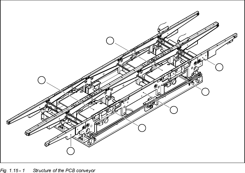
6WUXFWXUHRIWKH3&%FRQYH\RU
The placement system is supplied with a single conveyor as standard. A dual conveyor is
available as an option.
The left or the right side of the PCB conveyor can be used as the stationary side, as required.
1. Input area
2. Processing area 1
3. Intermediate area
4. Processing area 2
5. Output area
6. Lifting table (processing area 1)
7. Lifting table (processing area 2)
6
7
5
4
3
2
1