00191369-01.pdf - 第48页
1 Introduction User Manual HS-50 1.15 Overview of the modules - PCB conveyor Software Version 5.01 01/99 Issue 46 The convey or belts are driven by DC motor s. Eac h placeme nt area h as a lifti ng table for clamping the…
User Manual HS-50 1 Introduction
Software Version 5.01 01/99 Issue 1.15 Overview of the modules - PCB conveyor
45
2YHUY LHZRIWKHPRGXOHV3&%FRQY H\ RU
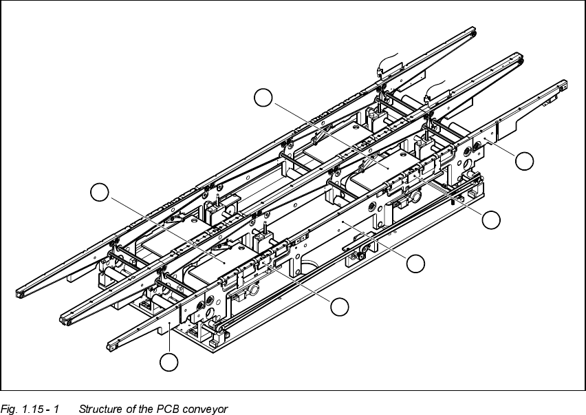
6WUXFWXUHRIWKH3&%FRQYH\RU
The placement system is supplied with a single conveyor as standard. A dual conveyor is
available as an option.
The left or the right side of the PCB conveyor can be used as the stationary side, as required.
1. Input area
2. Processing area 1
3. Intermediate area
4. Processing area 2
5. Output area
6. Lifting table (processing area 1)
7. Lifting table (processing area 2)
6
7
5
4
3
2
1

1 Introduction User Manual HS-50
1.15 Overview of the modules - PCB conveyor Software Version 5.01 01/99 Issue
46
The conveyor belts are driven by DC motors. Each placement area has a lifting table for
clamping the PCBs. The width of the PCB conveyor can be adjusted either
– via the menu or
– using the line computer
7HFKQLFDOGDWDVLQJOHFRQYH\RU
7HFKQLFDOGDWDGXDOFRQYH\RU
PCB format 50 mm x 50 mm to 368 mm x 460 mm
2" x 2" to 14.5 " x 18 "
PCB thickness 0.3 mm to 4.5 mm
Maximum PCB curvature On top: 4.5 mm - PCB thickness
On bottom: 0.3 mm + PCB thickness
Clearance underneath PCB Standard: 25 mm
Option: Up to 40 mm
PCB conveyor height 830 ± 15 mm (standard)
950 ± 15 mm (option) SMEMA
Type of interface Siemens (standard)
SMEMA (option)
Clear guide edge of component 3 mm
PCB changeover time 2.5 s
PCB format 50 mm x 50 mm to 368 mm x 216 mm
2" x 2" to 14.5 " x 8.5 "
Fixed edge of conveyor Right (standard), left (option)
Placement sequence per conveyor Synchronous: same or different
Asynchronous: same
PCB width per conveyor Synchronous: different
Asynchronous: same
Ink spot recognition Synchronous: not possible
Asynchronous: possible
Automatic width adjustment Synchronous: not possible
Asynchronous: possible
User Manual HS-50 2 Operational Safety
Software-Version 5.01Edition 01/99 2.1 Safety instructions
47
2SHUDWLRQDO6DIHW\
6DIHW\LQVWUXFWLRQV
&RQY HQWLRQVIRUWKHXVHRIKD]DUGV\ PEROV
This User Manual contains notes that must be observed to guarantee your personal safety and to
avoid damage to equipment. These notes are highlighted by warning triangles and are indicated
as follows according to the level of risk:
DANGER or
as used in this User Manual means that death, severe injury or considerable damage to equip-
ment may occur if the danger instructions are not followed.
WARNING or
as used in this User Manual means that death, severe injury or considerable damage to equip-
ment may occur if the warning instructions are not followed.
CAUTION or
as used in this User Manual means that slight injury or damage to equipment may occur if the cau-
tion instructions are not followed.
PLEASE NOTE
as used in this User Manual provides information on the product or indicates a part of the User
Manual that requires particular attention.
4XDOLILHGSHUVRQQHO
Qualified or adequately trained personnel means that these people are familiar with the setting up,
operation and maintenance of automatic placement systems and add-on devices and are suitably
qualified, e.g.
– have been trained, instructed or authorized to switch on and off, isolate, earth and identify elec-
trical circuits and system components in accordance with normal safety standards.