00191369-01.pdf - 第63页
User Manual HS-50 2 Operational Safety Software-Version 5.01Edition 01/99 2.2 Safety equipment 61 0DLQVZLWFKHPHUJHQF\VWRSPXVKURRPKHDGSXVKEXWWRQVSURWHFWLY H FRY HUV ZLWF K H V 3RVLWL RQRIPDL Q…
2 Operational Safety User Manual HS-50
2.2 Safety equipment Software-Version 5.01 Edition 01/99
60
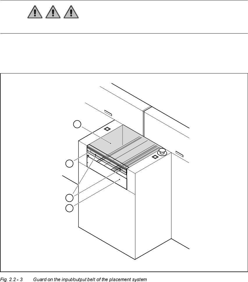
*XDUGRQWKHLQSXW RXWSXWEHOW
DANGER The guard must always be set to the height of the PCB to be pro-
cessed. Ensure that the gap between the guard and the safety bar is as small as possible.
Guards are fitted on the input and output belts of the PCB conveyor.
Å Set the height of the guard using the slots so that the PCB can pass through.
1. Safety bar (fixed)
2. Guard (adjustable)
3. Slots for adjusting the height
4. Cover
4
3
1
2
User Manual HS-50 2 Operational Safety
Software-Version 5.01Edition 01/99 2.2 Safety equipment
61
0DLQVZLWFKHPHUJHQF\VWRSPXVKURRPKHDGSXVKEXWWRQVSURWHFWLY H
FRYHUVZLWF KH V
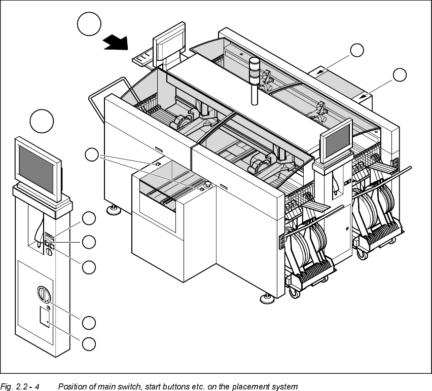
3RVLWLRQRIPDLQVZLWFKVWDUWEXWWRQVHWFRQWKHSODFHPHQWV\VWHP
1. Main switch
2. Stop buttons (black)
3. Start buttons (white)
4. Component counter
5. Service socket in the power supply unit behind the safety doors
3
3
A
A
1
3
4
2
5
3
2 Operational Safety User Manual HS-50
2.2 Safety equipment Software-Version 5.01 Edition 01/99
62
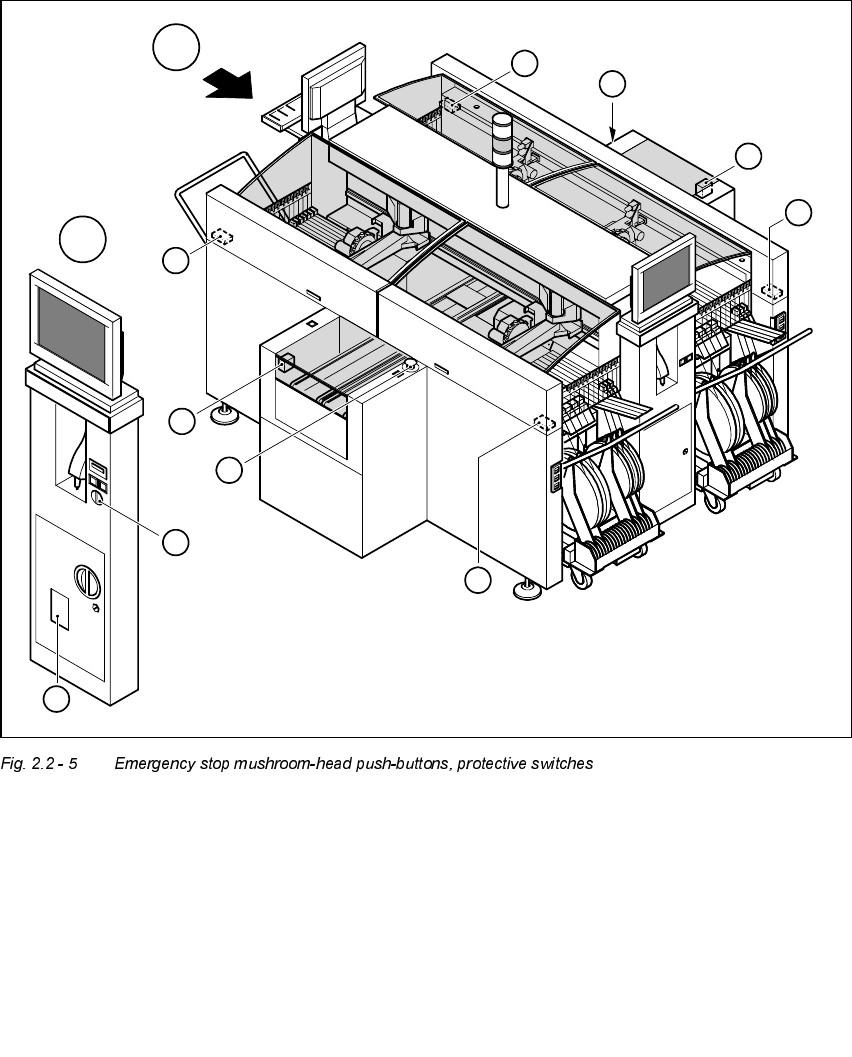
3RV LWLRQRIHPHUJHQF\VWRSPXVKU RRPKHDGSXVKEXWWRQVSURWHFWLYHVZLWFKHV
HWF RQWKHSO DFHPHQWV\VWHP
1. Emergency-stop buttons
2. Protective cover switches
3. Cover switches over the PCB conveyors
4. Protective contactor combination (PCC) in the power supply unit behind the safety doors
5. Key switch
Key switch opened: position 0 for normal mode
Key switch closed: position I for service purposes
1
1
A
A
4
3
3
2
5
2
2
2