00191369-01.pdf - 第64页
2 Operational Safety User Manual HS-50 2.2 Safety equipment Software-Version 5.01 Edition 01/99 62 3RV LW LRQRIHPHUJHQF\VWRSPXVKU RRP KHDGSXVKEXWW RQVSURWHFW LY HVZ LWFKHV HWF RQ WKHSO DFHP HQWV\…
User Manual HS-50 2 Operational Safety
Software-Version 5.01Edition 01/99 2.2 Safety equipment
61
0DLQVZLWFKHPHUJHQF\VWRSPXVKURRPKHDGSXVKEXWWRQVSURWHFWLY H
FRYHUVZLWF KH V
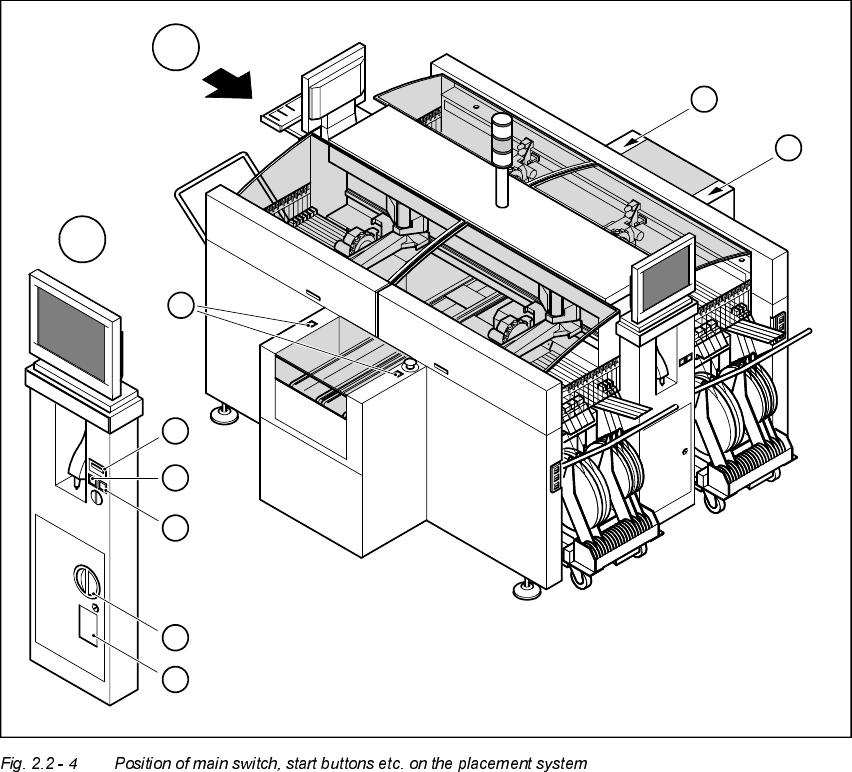
3RVLWLRQRIPDLQVZLWFKVWDUWEXWWRQVHWFRQWKHSODFHPHQWV\VWHP
1. Main switch
2. Stop buttons (black)
3. Start buttons (white)
4. Component counter
5. Service socket in the power supply unit behind the safety doors
3
3
A
A
1
3
4
2
5
3
2 Operational Safety User Manual HS-50
2.2 Safety equipment Software-Version 5.01 Edition 01/99
62
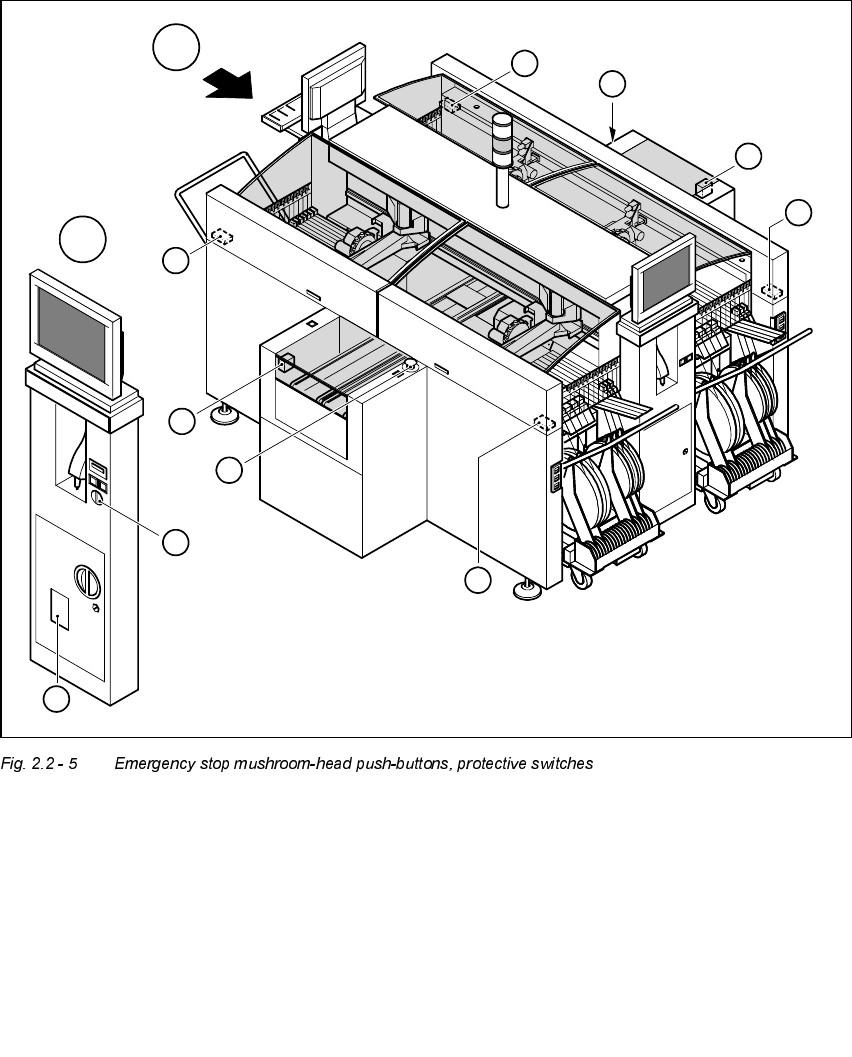
3RV LWLRQRIHPHUJHQF\VWRSPXVKU RRPKHDGSXVKEXWWRQVSURWHFWLYHVZLWFKHV
HWF RQWKHSO DFHPHQWV\VWHP
1. Emergency-stop buttons
2. Protective cover switches
3. Cover switches over the PCB conveyors
4. Protective contactor combination (PCC) in the power supply unit behind the safety doors
5. Key switch
Key switch opened: position 0 for normal mode
Key switch closed: position I for service purposes
1
1
A
A
4
3
3
2
5
2
2
2
User Manual HS-50 2 Operational Safety
Software-Version 5.01Edition 01/99 2.2 Safety equipment
63
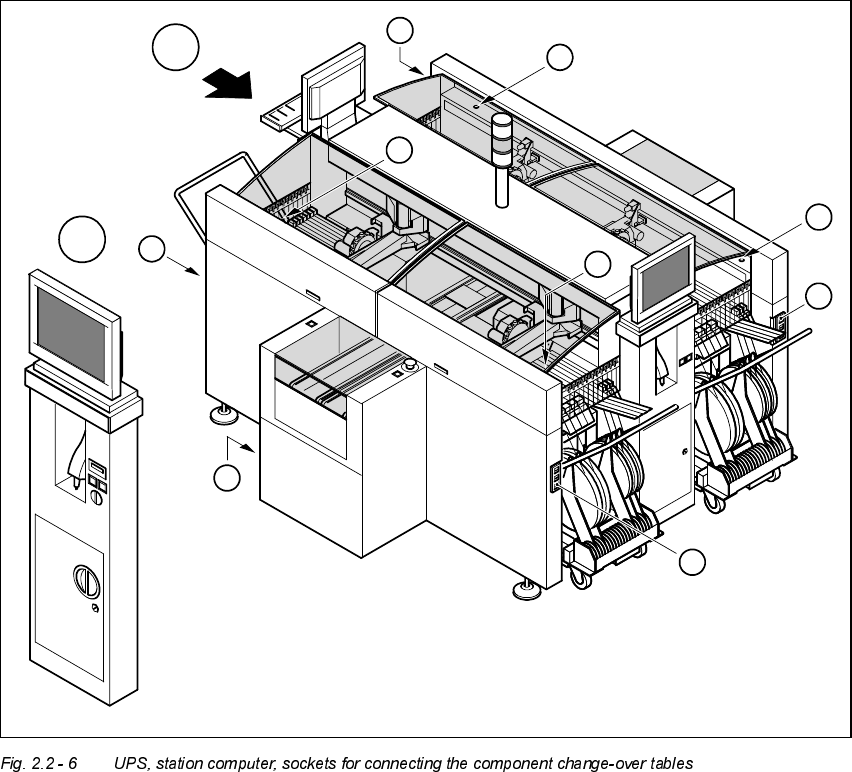
3RVLWLRQRI836VWDWLRQFRPSXWHUDQGVRFNHWVIRUFRQQHFWLQJWKHFRPSRQHQW
FKDQJHRYHUWDEOHVWRWKHSODFHPHQWV\VWHP
1. Socket for connecting the component change-over tables
2. Push-button for raising the component change-over tables with flap down and protective switch
3. UPS and station computer
A
A
1
1
1
1
2
2
2
2
3