00191369-01.pdf - 第74页
2 Operational Safety User Manual HS-50 2.3 Residual voltages i n the servo unit and discharge times when the placement system is switched offSoftware-Version 5.01 Edit ion 01/ 99 72 1. Po sition of the se rvo uni ts 2.…
User Manual HS-50 2 Operational Safety
Software-Version 5.01Edition 01/99 2.3 Residual voltages in the servo unit and discharge times when the placement system is switched
off
71
5HV LGXDOY ROWDJHVLQWKHV HUY RXQLWDQGGLVFKDUJH
WLPHVZKHQWKHSODF HPHQWV\V WHPLVVZLWFKHGRII
If the emergency stop mushroom-head push-button is pressed or the placement system is swit-
ched off, the 200 V link voltage for the gantry axes and 100 V link voltage for the star axes are
discharged to harmless residual voltages in a very short time.
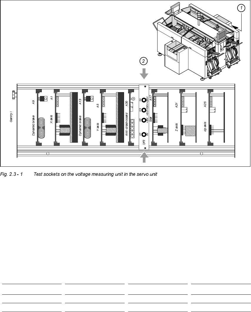
The voltages can be tapped at test sockets X1 - X4 on the voltage measuring unit in the servo
unit.
DANGER
The placement system is supplied with 3 x 204 V (US-Version), 3 x 400 v or 3 x 460 V ± 10%, 50/
60 Hz main power voltage. This means that some parts of the system carry potentially lethal volt-
ages - even when switched off at the main switch. Incorrect handling of the placement system
can therefore result in death or severe injury or considerable damage to equipment.
Å Always follow the applicable accident prevention and DIN regulations (particularly DIN EN
60 204, part 1).
Å The cover over the servo unit must only be opened by qualified and trained personnel.
1. Guard for 1 location 2. Guard for 6 - 10 locations
3. Guard for 11 - 20 locations
2 Operational Safety User Manual HS-50
2.3 Residual voltages in the servo unit and discharge times when the placement system is switched offSoftware-Version 5.01 Edition 01/
99
72
1. Position of the servo units
2. Voltage measuring unit on the servo unit
2SHUDWLQJYROWDJHVUHVLGXDOYROWDJHVDQGGLVFKDUJHWLPHVDIWHUSUHVVLQJWKH
HPHUJHQF\VWRSPXVKURRPKHDGSXVKEXWWRQ
7HVWVRFNHWV;;
;PHDVXUHGWR;
*1'
9ROWDJHLQQRUPDO
PRGH
5HVLGXDOYROWDJH
GXULQJHPHUJHQF\
VWRS 'LVFKDUJHWLPHV
X2 + 30 VDC + 30 VDC -
X3 + 100 VDC < 10 VDC 50 sec
X4 + 200 VDC < 10 VDC 7 sec
User Manual HS-50 2 Operational Safety
Software-Version 5.01Edition 01/99 2.4 Disabling the compressed air supply and releasing the pressure
73
5HVLGXDOYROWDJHVDQGGLVFKDUJHWLPHVDIWHUVZLWFKLQJRIIDWWKHPDLQVZLWFK
CAUTION The following conditions must be fulfilled before switching off the placement
system (apart from in emergencies) in order to avoid the loss of data:
– the placement system must have stopped transmitting machine, set-up and cluster data.
– the placement system must have stopped processing the PCBs.
– the placement system must have completed the start-up phase.
– the Windows NT operating system must have been shut down correctly.
'LVDEOLQJWKHFRPSUHVVHGDLUVXSSO\DQGUHOHDVLQJ
WKHSUHVVXUH
The compressed air operating pressure is permanently set to 5.3 bar. The position of the com-
pressed air unit is indicated by item 4 in the diagram. The compressed air supply to the placement
system may be interrupted using the shut-off valve (item 1 in the diagram).
Å Open the safety doors.
Å Turn the lever of the shut-off valve (item 1 in the diagram) from the vertical to the horizontal
position.
Å Check the operating pressure gauge and the pressure gauge for the compressed air supply to
the stopper (items 2 and 3 the diagram). When the placement system is switched on, the pres-
sure drops to 0 bar within 1 minute.
CAUTION When the machine is switched on, do not use the stop valve to interrupt the
compressed air supply for more than 30 minutes. If you need to shut off the pneumatic system for
longer in order to carry out maintenance or servicing work, you must switch the placement system
off at the main switch and disconnect it from the power supply.
7HVWVRFNHWV;;;
PHDVXUHGWR;*1'
5HVLGXDOYROWDJHZKHQPDLQ
VZLWFKLVVZLWFKHGRII 'LVFKDUJHWLPHV
X2 < 10 VDC < 2 sec
X3 < 10 VDC < 50 sec
X4 < 10 VDC < 7 sec