00191369-01.pdf - 第91页
User’s Manual SIPLACE HS-50 3 Introduction and Basic Concepts Software Vers ion SR.501.xx E dition 01/99 3.1 Mac hine Displays and Controls 89
3 Introduction and Basic Concepts User’s Manual SIPLACE HS-50
3.1 Machine Displays and Controls Software Version SR.501.xx Edition 01/99
88
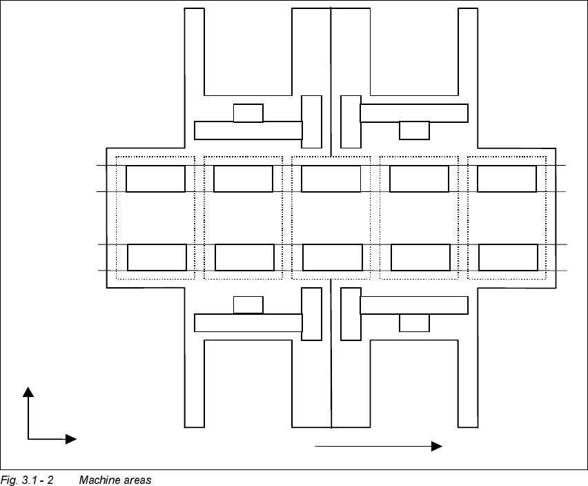
0DFKLQH$UHDV
The figure below provides a diagrammatic overview of the individual areas of a
SIPLACE HS-50 placement station.
The terms used in the figure to describe these areas are also used in the texts in the user
interface and in the User’s Manual.
([SODQDWLRQRI7HUPV
PA = processing area (1 or 2)
The conveyor is subdivided into the following sections in accordance with the machine
areas:
Input conveyor => Processing conveyor 1 => Intermediate conveyor => Processing
conveyor 2 => Output conveyor
Input
area
PA1 PA2
Output
area
Intermediate
area
Location 1 Location 2
Location 4 Location 3
Gantry 1
Gantry 3
Gantry 2
Gantry 4
Direction of transport
Conveyor 1
(right)
Conveyor 2
(left)
+X
+Y
User’s Manual SIPLACE HS-50 3 Introduction and Basic Concepts
Software Version SR.501.xx Edition 01/99 3.1 Machine Displays and Controls
89
3 Introduction and Basic Concepts User’s Manual SIPLACE HS-50
3.1 Machine Displays and Controls Software Version SR.501.xx Edition 01/99
90
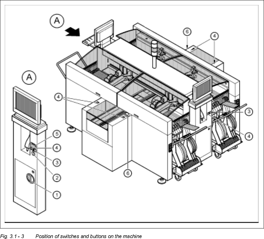
0DFKLQH6Z LWFKHVDQG%XWWRQV
The figure below presents the position of the switches and buttons on the machine.
.H\WR)LJXUH
A View of operating panel, left side
(1) Main switch
(2) Key-operated switch
(3) Stop button (black)
(4) Start button (white)
(5) Component counter
(6) EMERGENCY STOP button