00191369-01.pdf - 第92页
3 Introduction and Basic Concepts User’ s M anual SIPLACE HS -50 3.1 Machine Displays and Controls Software Version SR.501.xx Edition 01/99 90 0DFKLQH6Z L WFKHVDQG%XWWRQV The figure below pre sents the pos ition…
User’s Manual SIPLACE HS-50 3 Introduction and Basic Concepts
Software Version SR.501.xx Edition 01/99 3.1 Machine Displays and Controls
89
3 Introduction and Basic Concepts User’s Manual SIPLACE HS-50
3.1 Machine Displays and Controls Software Version SR.501.xx Edition 01/99
90
0DFKLQH6Z LWFKHVDQG%XWWRQV
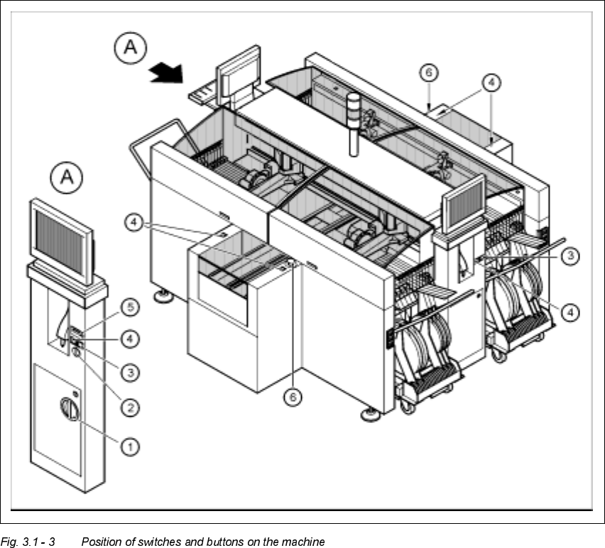
The figure below presents the position of the switches and buttons on the machine.
.H\WR)LJXUH
A View of operating panel, left side
(1) Main switch
(2) Key-operated switch
(3) Stop button (black)
(4) Start button (white)
(5) Component counter
(6) EMERGENCY STOP button
User’s Manual SIPLACE HS-50 3 Introduction and Basic Concepts
Software Version SR.501.xx Edition 01/99 3.1 Machine Displays and Controls
91
WARNING
Only appropriately qualified personnel are permitted to use the key-operated switch for service
or maintenance work. The key must be removed to prevent unauthorized access as otherwise
serious injury to personnel or damage to the machine may occur.
0DLQ)DXOW,QGLFDWRU
The main fault indicator (see Figure 3.1 - 1) contains 2 fault indicator lights (white) together
with an operating indicator light (green)
The operating indicator light is located between the two fault indicator lights. This indicates
whether the machine is in production or wait mode.
The nature and location of any malfunction can be identified using the operating indicator
light (flashing, glowing etc.) and the two fault indicator lights.
The following section describes the information provided by the two fault indicator lights.
NOTE
The operating statuses (or their meanings) of the two fault indicator lights can be individually
programmed to respond to local circumstances (see the description of the "Programmable
Operating Statuses" in the next section).