00194705-0102_AI_1WireBus_DE+EN.pdf - 第44页
Retrofit instructions: New 1-wire wiring for the SIPLACE X-series 11/2005 Edition 44 T asks (1) Controlling the nozzle changer , 6/12 C&P hea ds (1st and 2nd row) (2) Controlling the nozzle cha nger , 20 C&P head…
Retrofit instructions: New 1-wire wiring for the SIPLACE X-series
11/2005 Edition
43
2 Retrofit instructions:
New 1-wire wiring for the SIPLACE
X-series
2.1 Advantages of the new wiring
– The new wiring for the 1-wire bus eliminates internal communication problems.
– The cable for the 1-wire bus is removed from the machine CAN bus cable in the vicinity of the
locations and is run in specially shielded cables.
– The quality of the 24V supply is also improved by a voltage regulator on the control board in
the nozzle changer.
2.2 Variants of the new wiring
There are two variants of the new wiring. If a part of the older variant (there are around 30 ma-
chines in the field) fails and has to be replaced, then the entire wiring must be converted to the
new variant. 2
The 24 V supply must be fitted for both variants. 2
2.3 One-wire bus
Introduction of the message loop into software version 505 (601) required the number of inputs
and outputs to be reduced or an additional I/O module to be installed. The "one-wire bus system"
was introduced to take account of the space available in the machine and on cost grounds.
The one-wire bus controls the nozzle changer in all 4 sectors, transfers the temperature values
from the sensors to the head plates and carries the gantry data.
Retrofit instructions: New 1-wire wiring for the SIPLACE X-series
11/2005 Edition
44
Tasks
(1) Controlling the nozzle changer, 6/12 C&P heads (1st and 2nd row)
(2) Controlling the nozzle changer, 20 C&P heads (1st and 2nd row), with magazine scan
(3) 2 temperature sensors are fixed to the head board for each gantry.
(4) The gantry identification is saved on an EEPROM.
(We distinguish between board gantry CFK 02, DTC gantry CFK 04 and gantry CFK 06. It
therefore follows that the machine database for the dynamic parameters of the main axes that
is loaded differs according to the type of gantry).
(5) Option: Scan of the reject bin in all 4 sectors
2.3.1 Structure of the 1-wire bus
As the name suggests, the data is transferred on one wire. The data is therefore sent to the sub-
system serially.
The 1-wire bus is used for non-time-critical sequences and can be implemented as a single master
bus with "any number" of slaves (stations).
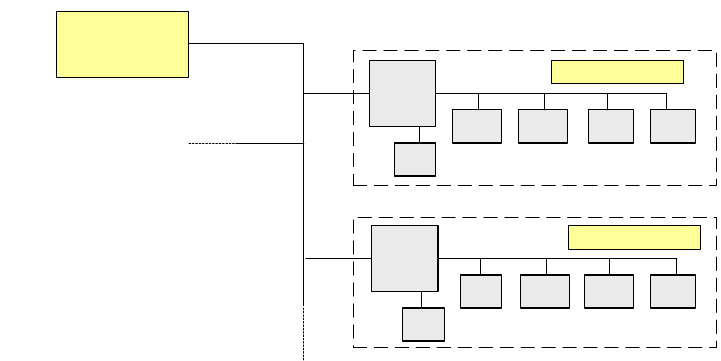
2.3.1.1 Basic structure
The 1-wire bus essentially consists of a master with an EEPROM (control unit) that controls vari-
ous sub-modules, such as the A/D converter, EEPROM, temperature and I/O modules. There is
a coupler connected upstream of each communication branch. This coupler opens the branch for
the exchange of data.
Fig. 2.3 - 1 Principle of the 1-wire bus
2
2
Slave
Master
Coupler
E²
A/D A/DA/D I/O
Coupler
E²
°C I/O°C
E²
Slave

Retrofit instructions: New 1-wire wiring for the SIPLACE X-series
11/2005 Edition
45
2.4 Parts required
2
2
2.4.1 Tools and consumables required
Set of hexagon socket spanners 2
Set of screwdrivers 2
Set of diagonal cutters 2
Cable ties 2
2
2
2
2
2
X4 retrofit package for the 1-wire bus, Cat 5
2 Wago terminal
2 Jumper for Wago terminal
2 24 V cable, 2-wire b/w
Item no.: 3009826-xx
2 24 V cable, 2-wire b/w
Item no.: 3009839-xx
2 5-pole Phoenix connector (female)
2 CAT 5 cable, 3m, to the 1-wire CAT5 distributor
Item no.: 3041626-xx
2 CAT 5 cable, 3m, to the 1-wire hub
Item no.: 3041627-xx
2 CAT 5 cable, 3m, to the 1-wire hub
Item no.: 3041628-xx
2 CAT 5 cable, 3m, to the 1-wire CAT5 gantry
Item no.: 3041629-xx
2 Board, 1-wire interface CAT5
Item no.: 03041578-02
4 Board, 1-wire CAT5 gantry
Item no.: 03042214-0102
2 1-wire CAT5 distributor
Item no.: 03040219-01
4 1-wire hub CAT5
Item no.: 03041473-02
2 1-wire jumper for cable between gantry boards
Item no.: 03042347-01
12 Self-adhesive cable clips
12 Cable ties
1 Retrofit Instructions
4 Retaining plate with modification 402012
8 Screws for the hubs on the retaining plate