00194705-0102_AI_1WireBus_DE+EN.pdf - 第66页
Retrofit instructions: New 1-wire wiring for the SIPLACE X-series 11/2005 Edition 66 The design of the 1-wire bus is exactly the same in P A2, depending on the machine configuration (1 or 2 gantries). Description of the …
Retrofit instructions: New 1-wire wiring for the SIPLACE X-series
11/2005 Edition
65
2.9 Variant 2
2.9.1 1-wire bus in the SIPLACE X
On the SIPLACE X machine, the 1-wire bus runs via a separate CAT5 cable from the sub or main
distributor to the cable and hose carrier interface. From the cable and hose carrier interface to the
head interface, the 1-wire bus runs in the cable and hose carrier. This means that the structure of
the cable run has changed, but the function remains the same.
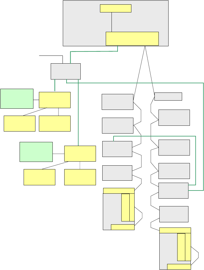
Fig. 2.9 - 1 Overview of the one-wire stations with reference to PA1 on the SIPLACE X
Vision control
unit,
sector 4
Conveyor
control unit
A x is u n it
PA 1
COM Board
I/O SUB m odule,
sector 4
One-wire bridge
(d riv e r)
Nozzle changer
hub (coupler),
gantry 4
C O table 4,
ta p e c u tte r
Conrol board
N C (C & P 2 0 ),
ro w 1
Control board
N C (C & P 2 0 ),
ro w 2
Trailing interface,
gantry 4
C O table 1,
ta p e c u tte r
Trailing interface,
gantry 1
Tem p.sensor
Head
plate
Tem p.sensor
O ption: C heck reject bin
or term inating plug
Attention: no C AN -
term inating resistor
TQM Module
(M a s te r)
RS232
Machine CAN bus
1-wire CAT5,
gantry 4
Head interface
1-wire CAT5,
gantry 4
Tem p.sensor
Head
plate
Tem p.sensor
G antry
recognition
Head interface
1-wire CAT5
distributor
24V for the nozzle changer
1-wire CAT5 cable
1-wire CAT5 cable
1-wire CAT5 cable
1-wire CAT5 cable
1-wire CAT5 cable
Nozzle changer
hub (coupler),
gantry 1
NC control board
(C &P20),
ro w 2
NC conrol board
(C & P 2 0 ),
ro w 1
O ption: C heck reject bin
or term inating plug
Attention: no CAN-
te rm in a tin g re s is to r
Gantry
recognition

Retrofit instructions: New 1-wire wiring for the SIPLACE X-series
11/2005 Edition
66
The design of the 1-wire bus is exactly the same in PA2, depending on the machine configuration
(1 or 2 gantries).
Description of the functions: 2
Each 1-wire bus is assigned a fixed CAN ID when the machine is switched on.
1-wire in PA1 --> CAN ID: 07d0
1-wire in PA2 --> CAN ID:07c0
While the bus system is initializing, each station logs onto the master and the bus switches to
standby.
At rest, the voltage level on the 1-wire bus is 5V.
The bus can be initialized again using the CACCIA tool (see Checking the functions and trouble-
shooting during servicing).
Connector assignment: machines/CAN bus:
Fig. 2.9 - 2 Pin assignment: sub D connector
Components of the 1-wire bus 2
Modules:
(1) 1-wire RS232 bridge on the SUB/MAIN module (subsequently integrated into the I/O module)
(2) 1-wire CAT5 gantry on the cable and hose carrier interface (board between CAN bus and
cable and hose carrier interface)
(3) 1-wire CAT5 distributor
(4) 1-wire hub nozzle changer
(5) Nozzle changer control board (integrated into the NC, not for DLM heads)
(6) 1 set of temperature sensors (must all be replaced at the same time since they are dependent
on the serial number)
(7) Gantry identification (EEPROM)
120
Ohm
CAN Interrupt95
+24V 1-wire-Bus89
Power Fail74
CAN Reset68
GND53
CAN High47
CAN Low32
GND26
1-wire-Bus 11
AderPin
PIN 1 on HF machines only
Retrofit instructions: New 1-wire wiring for the SIPLACE X-series
11/2005 Edition
67
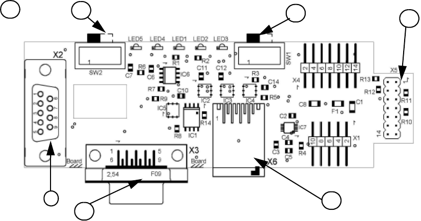
Fig. 2.9 - 3 1-wire RS232 interface (03041578-01)
(1) CAN bus interface to the I/O module (2) RS 232 interface
(3) CAN bus interface to the machine (4) Switch position varies according to the I/O
module release
(5) MA / PC switch must be
set to MA (Machine)
(6) CAT5 cable connection
LED 1, NC 1/3 LED 2 Temperature sensors
LED 3, NC 4/2 LED 4 Green "OK"
LED 5 Green "Error"
4
1
2
3
1
5
6