00194705-0102_AI_1WireBus_DE+EN.pdf - 第68页
Retrofit instructions: New 1-wire wiring for the SIPLACE X-series 11/2005 Edition 68 Fig. 2.9 - 4 1-wire CA T5 distributor (0304021 9-01) Fig. 2.9 - 5 1-wire gantry board (03042214-01) 2 CA T 5 ca ble input from the RS 2…
Retrofit instructions: New 1-wire wiring for the SIPLACE X-series
11/2005 Edition
67
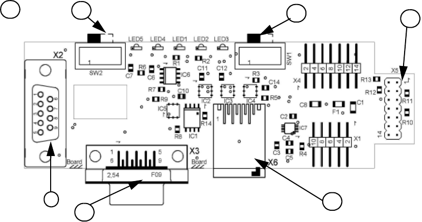
Fig. 2.9 - 3 1-wire RS232 interface (03041578-01)
(1) CAN bus interface to the I/O module (2) RS 232 interface
(3) CAN bus interface to the machine (4) Switch position varies according to the I/O
module release
(5) MA / PC switch must be
set to MA (Machine)
(6) CAT5 cable connection
LED 1, NC 1/3 LED 2 Temperature sensors
LED 3, NC 4/2 LED 4 Green "OK"
LED 5 Green "Error"
4
1
2
3
1
5
6
Retrofit instructions: New 1-wire wiring for the SIPLACE X-series
11/2005 Edition
68
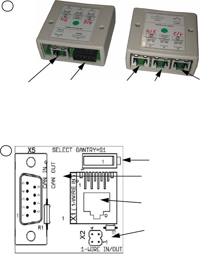
Fig. 2.9 - 4 1-wire CAT5 distributor (03040219-01)
Fig. 2.9 - 5 1-wire gantry board (03042214-01)
2
CAT 5 cable input
from the RS 232
interface
24 V input for
NC
CAT5 output to
the NC hub,
gantry 3 or 4
CAT 5 output to
the 1-wire gan-
try board
CAT5 output to
the NC hub,
gantry 1 or 2
3
Switch: Down position - gantry 1/2
Up position - gantry 3/4
This board is seated directly on the CAN
bus connector on the cable and hose
carrier interface.
CAT5 cable connection from the 1-wire
CAT5 distributor
X2 connection to the second gantry in
the placement area.
Retrofit instructions: New 1-wire wiring for the SIPLACE X-series
11/2005 Edition
69
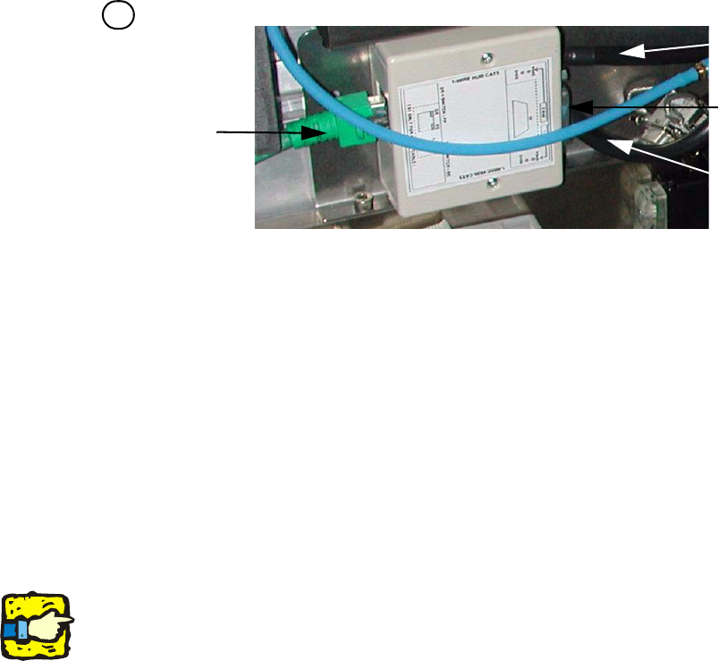
Fig. 2.9 - 6 1-wire hub, NC (03041473-02)
2
2
2
The switch for the location coding (HF only) will be omitted in the future.The coding to indicate the
location at which the nozzle changer is installed is hardware-coded in the connector for the loca-
tion concerned (X112 / X122 / X132 / X142) on the HF and SIPLACE X. 2
2
(1) CAT 5 cable input from the CAT 5 distributor (2) SUB-D connector option (reject bin)
(3) NC 1 connection (4) NC 2 connection
Right-hand side: Display (2 LEDs) for NC C&P6/12
NC light barrier open/closed and NC valve open/closed for each row Left-hand side: Display (2
LEDs) for the reject bin option
Yellow LED: reject bin for components connected
Green LED: reject bin for nozzles connected
4
1
2
3
4