00197787-02_SI_SIPLACE_HeadVerification_EN.pdf - 第15页
3 Head verification principles 3.1 Starting the offline head verification Software Manual SIPLACE Head Verification 03/2018 15 3.1.3.3 Checking / modifying the zero point correction The individual measurements of a head …
3 Head verification principles
3.1 Starting the offline head verification
14 Software Manual SIPLACE Head Verification 03/2018
3.1.3 Helpful HCS functions
3.1.3.1 Adding users
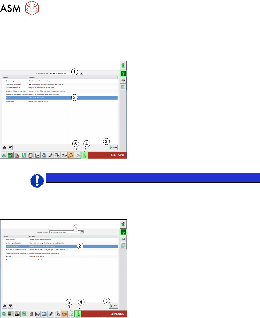
The operator is set up by default. If more persons are required, they can be added to the list using
the Add user function:
Fig.9: Add user function
► Click the Test bench service icon(4).
► From the list, select Test bench configura-
tion(1).
► Select the Add user function(2).
► Click the Start button(3).
► Enter a name and click OK.
ð The user is now available in the Tester list on
the Meta data tab.
► Click the Test bench inspection icon(5) to re-
turn to the Meta data tab.
NOTICE
Removing users
To remove a user, select the Remove user function and proceed as described for Adding
users.
3.1.3.2 Modifying the test bench configuration
Fig.10: Test bench machine ID function
► Click the Test bench service icon(4).
► From the list, select Test bench configura-
tion(1).
► Select the Test bench machine ID function(2).
► Click the Start button(3).
► Enter the HCS ID written on the type plate or on
the label below the pneumatic unit and click OK.
► Click the Test bench inspection icon(5) to re-
turn to the Meta data tab.
3 Head verification principles
3.1 Starting the offline head verification
Software Manual SIPLACE Head Verification 03/2018 15
3.1.3.3 Checking / modifying the zero point correction
The individual measurements of a head verification process are performed using the data that is
stored in the SIPLACEmachine configuration. In some cases, the data readout from the machine
does not match the machine data of the HCS. Therefore, it is recommended to check / modify the
data before running the head verification.
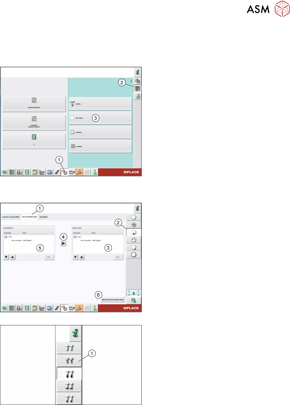
Fig.11: Check sensors and functions
► Click the Check sensors and functions icon(1).
► Click the Check sensors and functions of spe-
cific components icon(2).
► Open the head functions for the installed
head(3), for example, the CPP head.
Checking the zero correction data of the Z-axis
Fig.12: Zero correction data of Z-axis of C&P heads
For C&P heads, proceed as follows:
► Log on as machine service.
► Click the Check sensors and functions of Z-
axis icon(2).
► Click the Zero correction data tab(1).
► Compare the machine data(3) to the head
EPROM data(5).
► If the head EPROM data(5) is to be used, click
the arrow(4) to overwrite the machine data(3) or
click Edit… and enter the zero correction data.
► To save your settings, click the Write head and
machine data button(6).
Fig.13: Zero correction data of Z-axis of P&P modules
► For P&P modules, proceed as for C&P heads,
but note that the Check sensors and functions
of Z-axis icon(1) is different.
3 Head verification principles
3.1 Starting the offline head verification
16 Software Manual SIPLACE Head Verification 03/2018
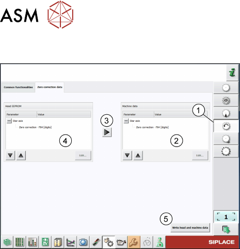
Checking the zero correction data of the star axis
Fig.14: Zero correction data of star axis of C&P heads
► Click the Check sensors and functions of star
axis icon(1).
► Click the Zero correction data tab.
► Compare the machine data(2) to the HCS
data(4).
► If the head EPROM data(2) is to be used, click
the arrow(3) to overwrite the machine data or
click Edit… and enter the zero correction data.
► To save your settings, click the Write head and
machine data button(5).