00197787-02_SI_SIPLACE_HeadVerification_EN.pdf - 第23页
4 Offline head verification 4.1 Preliminary steps Software Manual SIPLACE Head Verification 03/2018 23 4 Offline head verification 4.1 Preliminary steps NOTICE Complete head required A comprehensive C&Phead verifica…
3 Head verification principles
3.3 Head verification software
22 Software Manual SIPLACE Head Verification 03/2018
3.3.6 End of measurement – Summary
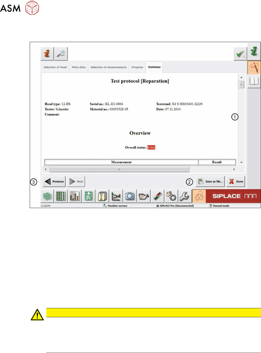
When all measurements are finished, the system automatically opens the protocolview(1).
Fig.23: Summary tab
1 Protocol overview
2 Save as file button
3 Previous button
If the Overall status shows an ‘Error’, one or more tests failed or could not be finished.
Following the Overall status, an overview of all measurements is displayed indicating if a meas-
urement was successful or failed, or if the test was skipped. Following that, test details for each
measurement are shown.
The protocol is automatically saved to a PDF file in D:\Protocols to a specified folder correspond-
ing to the verified head. Nevertheless, you can still save the protocol to a favored target folder:
► To close the current head verification, click the Done button.
CAUTION
Head verification process data removed
If you click the Done button, the current head verification will be closed and all temporary
data will be deleted. In this case, the result is only available in the PDF that is automatically
saved to D:\Protocols.
► Only click Done when you are sure to close the current head verification.

4 Offline head verification
4.1 Preliminary steps
Software Manual SIPLACE Head Verification 03/2018 23
4 Offline head verification
4.1 Preliminary steps
NOTICE
Complete head required
A comprehensive C&Phead verification requires a component camera.
For the offline head verification, the HCS needs to be prepared in accordance with the head to be
verified. The table below provides an overview of the preparations required.
For more information, see the SIPLACE Head Care Station User Manual [00197262-04].
Task C&P20A C&P20P CPP P&P
(TH)
► Install the "Stopper CP20-CPP”. x x x
► Install the "Stopper P+P". --- --- --- x
► Prepare the "Calibration tool pocket" for
"Calibration tool version SST23".
x x --- ---
► Prepare the "Calibration tool pocket" for
"Calibration part version 3".
--- --- x ---
► Connect the cable at the back to the "Ad-
apter-LP CPP/CP20-HCSII".
x x x ---
► Connect the cable at the back to the "Board
Adapter-LP TWIN-HCSII".
--- --- --- x
► Set the switch at the back. 40V 40V 150V ---
► Mount the head equipped with nozzles. 1235 4235 2057 517
► Connect the camera cables. 2x 2x 2x ---
► Connect the flat ribbon cables. 2x 2x 2x 2x
► Connect the compressed air / vacuum pump
supply.
2x 2x 2x 2x
► Connect the exhaust hose. x x x x
► Switch on the control box. x x x x
► Switch on the head. x x x x
► Start the Test Bench software. x x x x
► Log in as “Machine Service”. x x x x
► Check / adjust the zero point corrections. Z / Star Z / Star Z / Star D
► Start the head verification. x x x x
► Adjust the force sensor. x x x x
► Open the main compressed air supply at the
back.
x x x x
► Open the valves for the required compressed
air / vacuum supply.
x x x x
► Check / adapt the meta data x x x x
4 Offline head verification
4.2 Available measurements for C&P20A
24 Software Manual SIPLACE Head Verification 03/2018
4.2 Available measurements for C&P20A
Required tools
●
1x endurance run unit [03086515-xx]
●
1x CP20 – CPP stopper [03095249-xx]
●
1x calibration tool pocket [03086419-xx]
●
1x nozzle centering unit [03086323-xx]
●
1x calibration jig version SST23 [03034148-xx]
●
20x Nozzle 1235 [03015222-xx]
●
1x vacuum measurement unit [03085726-xx]
●
20x Nozzle 1069 [03094112-xx]
●
1x force measurement unit [03086502-xx]
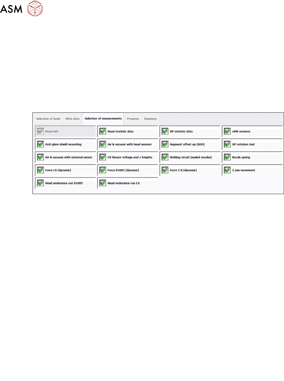
Verification workflow
Fig.24: Available measurements for C&P20A
1 Head info
2 Head statistic data
3 DP statistic data
4 eSW versions
5 Anti-glare shield mounting
See 6.4 "Anti-glare shield mounting" [}42]
6 Air & vacuum with head sensors
See 6.2 "Air & vacuum with head sensor" [}37]
7 Segment offset up (SOO)
See 6.21 "Segment offset up (SOO)" [}78]
8 DP rotation test
See 6.8 "DP rotation test" [}48]
9 Air & vacuum with external sensor
See 6.3 "Air & vacuum with external sensor" [}40]
10 CS Sensor voltage and z-heights
See 6.5 "CS Sensor voltage and z-heights" [}44]
11 Holding circuit (sealed nozzles)
See 6.17 "Holding circuit (sealed nozzles)" [}68]
12 Nozzle spring
See 6.18 "Nozzle spring" [}70]
13 Force LS (dynamic)
See 6.11 "Force measurement for C&P heads" [}54]
14 Force 01005 (dynamic)
See 6.11 "Force measurement for C&P heads" [}54]
15 Force 5N (dynamic)
See 6.11 "Force measurement for C&P heads" [}54]
16 Z axis movement
See 6.22 "Z-axis movement" [}81]
17 Head Endurance Run 01005
See 6.14 "Head endurance run 01005" [}60]
18 Head Endurance Run LS
See 6.16 "Head endurance run LS" [}65]