00197787-02_SI_SIPLACE_HeadVerification_EN.pdf - 第28页
4 Offline head verification 4.5 Available measurements for TH 28 Software Manual SIPLACE Head Verification 03/2018
4 Offline head verification
4.5 Available measurements for TH
Software Manual SIPLACE Head Verification 03/2018 27
4.5 Available measurements for TH
Required Tools
●
1x endurance run unit [03086515-xx]
●
1x Nozzle 517 [03012042-xx]
●
1x calibration tool pocket [03086419-xx]
●
P+P stopper [03119655-xx]
●
1x calibration part version 3 [03010565-xx]
●
1x force measurement unit [03086502-xx]
●
1x Nozzle 504
– Adapter for 9xx nozzle [00330027-xx]
– Adapter nozzle interface [03011583-xx]
– Nozzle 904 [00322602-xx]
●
1x vacuum measurement unit [03085726-xx]
Verification workflow
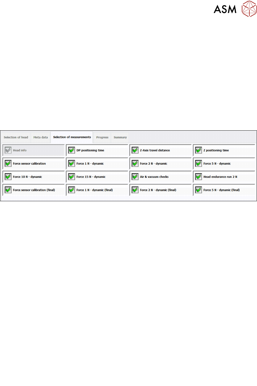
Fig.27: Available measurements for P&P module
1 Head info
2 DP positioning time
See 6.7 "DP positioning time" [}47]
3 Z-Axis travel distance
See 6.23 "Z-Axis travel distance" [}83]
4 Z positioning time
See 6.25 "Z positioning time" [}87]
5 Force sensor calibration See 6.13 "Force sensor calibration / Force sensor cali-
bration (final)" [}58]
6 Force 1N – dynamic
See 6.12 "Force measurement P&P module (TH)" [}56]
7 Force 2N – dynamic
See 6.12 "Force measurement P&P module (TH)" [}56]
8 Force 5N – dynamic
See 6.12 "Force measurement P&P module (TH)" [}56]
9 Force 10N – dynamic
See 6.12 "Force measurement P&P module (TH)" [}56]
10 Force 15N – dynamic
See 6.12 "Force measurement P&P module (TH)" [}56]
11 Air & vacuum checks
See 6.1 "Air & vacuum checks" [}35]
12 Head endurance run 2N
See 6.15 "Head endurance run 2N" [}63]
13 Force sensor calibration (final) See 6.13 "Force sensor calibration / Force sensor cali-
bration (final)" [}58]
14 Force 1N – dynamic (final)
See 6.12 "Force measurement P&P module (TH)" [}56]
15 Force 2N – dynamic (final)
See 6.12 "Force measurement P&P module (TH)" [}56]
16 Force 5N – dynamic (final)
See 6.12 "Force measurement P&P module (TH)" [}56]

4 Offline head verification
4.5 Available measurements for TH
28 Software Manual SIPLACE Head Verification 03/2018

5 Online head verification workflow
5.1 Preliminary steps
Software Manual SIPLACE Head Verification 03/2018 29
5 Online head verification workflow
5.1 Preliminary steps
Preparatory tasks
If the head verification is performed systematically in your production environment, it is recommen-
ded to prepare complete magazines with the required nozzle types to reduce the time that is re-
quired to change the nozzle changer configuration.
Vacuum pump operation
The following notes apply primarily to heads of type C&P20x as the standard configuration of this
head is set up for the vacuum pump operation:
NOTICE
Influence from 2
nd
gantry
On machines equipped with a vacuum pump, the vacuum is no longer generated for the in-
dividual head but for the whole placement area instead. For the head verification process, it
is crucial to eliminate any influence from the gantry or head which is currently not verified.
If the head verification is to be performed in a placement area where a vacuum pump is
used to generate the vacuum, one of the following nozzle configurations is recommended
for the heads which are not to be verified:
► Closed red vacuum nozzles to close off the vacuum system (preferred solution)
► Nozzles with small cross-section, e.g. 4104 or 4105 (acceptable solution due to small
opening)
NOTICE
Disabled segments not verified
If segments have been disabled, these segments are omitted from the head verification
process. No measurement will be performed for these segments. However, an error will be
shown for each omitted segment, indicated by a red cross, as the measurements are miss-
ing.
Segment 1 cannot be disabled, as this is required for the general functioning of the head.