00197787-02_SI_SIPLACE_HeadVerification_EN.pdf - 第49页
6 Description of the test results 6.8 DP rotation test Software Manual SIPLACE Head Verification 03/2018 49 6.8.3 Interpretation of the results obtained ‘DP rotation angle’ error for all segments Cause Solution Possible …
6 Description of the test results
6.8 DP rotation test
48 Software Manual SIPLACE Head Verification 03/2018
6.8 DP rotation test
6.8.1 Measurement principle
The DP rotation measurement is used to verify the DP position.
During the measurement, the calibration tool is picked up, moved to the component camera and
positioned at 4°(4000 digits). The component camera then captures a live image of the calibration
tool and checks if the position is within the allowed limits.
6.8.2 Measurement result
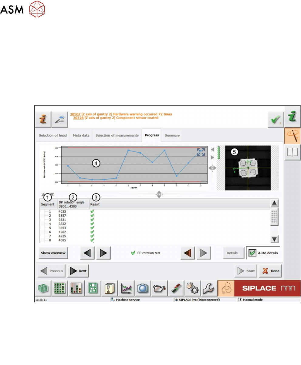
Fig.40: Result view – DP rotation test
1 Measured Segment
2 DP rotation angle of the calibration tool determined by the component camera.
3 Result view indicating if the values are within (green tick) or outside (red cross) the limits.
4 Graph showing the measured DP rotation angle for each segment.
5 Live image of the calibration tool.

6 Description of the test results
6.8 DP rotation test
Software Manual SIPLACE Head Verification 03/2018 49
6.8.3 Interpretation of the results obtained
‘DP rotation angle’ error for all segments
Cause Solution
Possible contamination of component camera ► Clean the lens or replace the component
camera.
‘DP rotation angle’ error for individual segments
Cause Solution
DP does not rotate reliably ► Replace the segment (DP).
Calibration component rotates on nozzle ► Check if the nozzle is dirty and clean it if
necessary.
► Check the nozzle seat.
► Check the vacuum supply.
6 Description of the test results
6.9 Dp- / Z-Positioning
50 Software Manual SIPLACE Head Verification 03/2018
6.9 Dp- / Z-Positioning
6.9.1 Measurement principle
The Dp-/Z-Positioning measurement checks the deviation between the Z-axis down light barrier
and the component sensor, in accordance with the angle setting of the segment. Each segment is
moved down and moved to an angle of 0°, 60°, 120°, 180°, 240° and 300°. For each angle, the
position is determined where the nozzle interrupts the beam of the component sensor and when
the light barrier is activated.
6.9.2 Measurement result
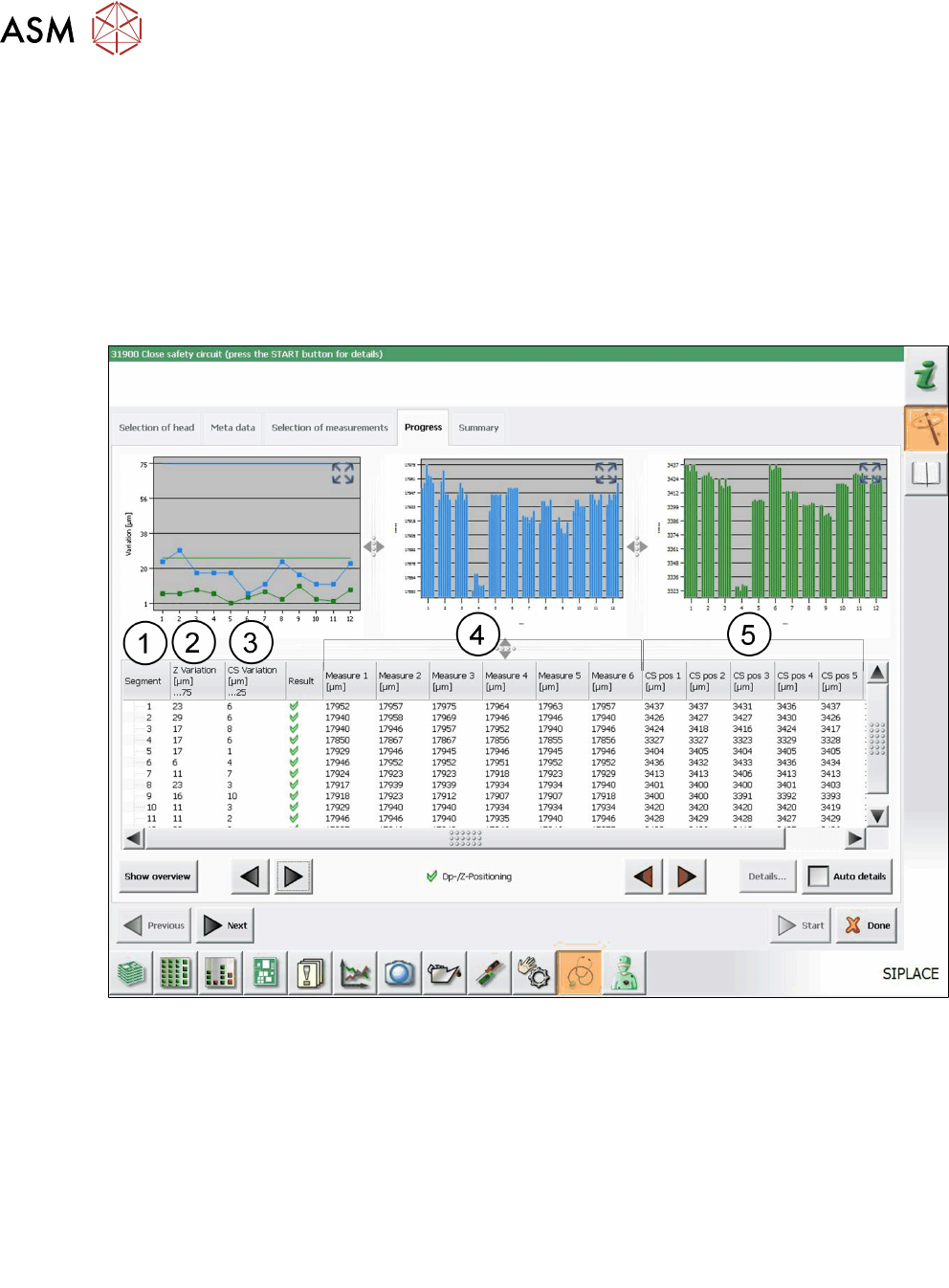
Fig.41: Result view – Dp-/Z-Positioning test
1 Measured Segment
2 Z Variation shows the difference between smallest and biggest value measured for Meas-
ure 1-6:
ZVariation = Measure
1-6max
- Measure
1-6min
3 CS Variation shows the difference between smallest and biggest value measured for
CSpos1-6:
CS Variation = CS
pos1-6max
- CS
pos1-6min
4 Measure 1-6 show the values measured when the Z-axis light barrier was interrupted.
5 CS pos 1-6 show the values measured when the component sensor was interrupted.