00197787-02_SI_SIPLACE_HeadVerification_EN.pdf - 第53页
6 Description of the test results 6.10 Filter Disc Software Manual SIPLACE Head Verification 03/2018 53 6.10.3 Interpretation of the results obtained ‘Filter disk OK’ error for all segments Cause Solution Holding circuit…
6 Description of the test results
6.10 Filter Disc
52 Software Manual SIPLACE Head Verification 03/2018
6.10 Filter Disc
6.10.1 Measurement principle
The Filter disk measurement checks the filter discs on the C&P20A head segments for pollution
and disc seal tightness.
During the measurement, all nozzles are returned to the nozzle changer before an air blast of
400mbar is applied to each segment to blow off loosely fitted or damaged filter discs and to clean
the remaining filter discs. Finally, all segments are visually checked for missing filter discs. The
segments to which a filter disc is still attached are visually checked again for contamination.
6.10.2 Measurement result
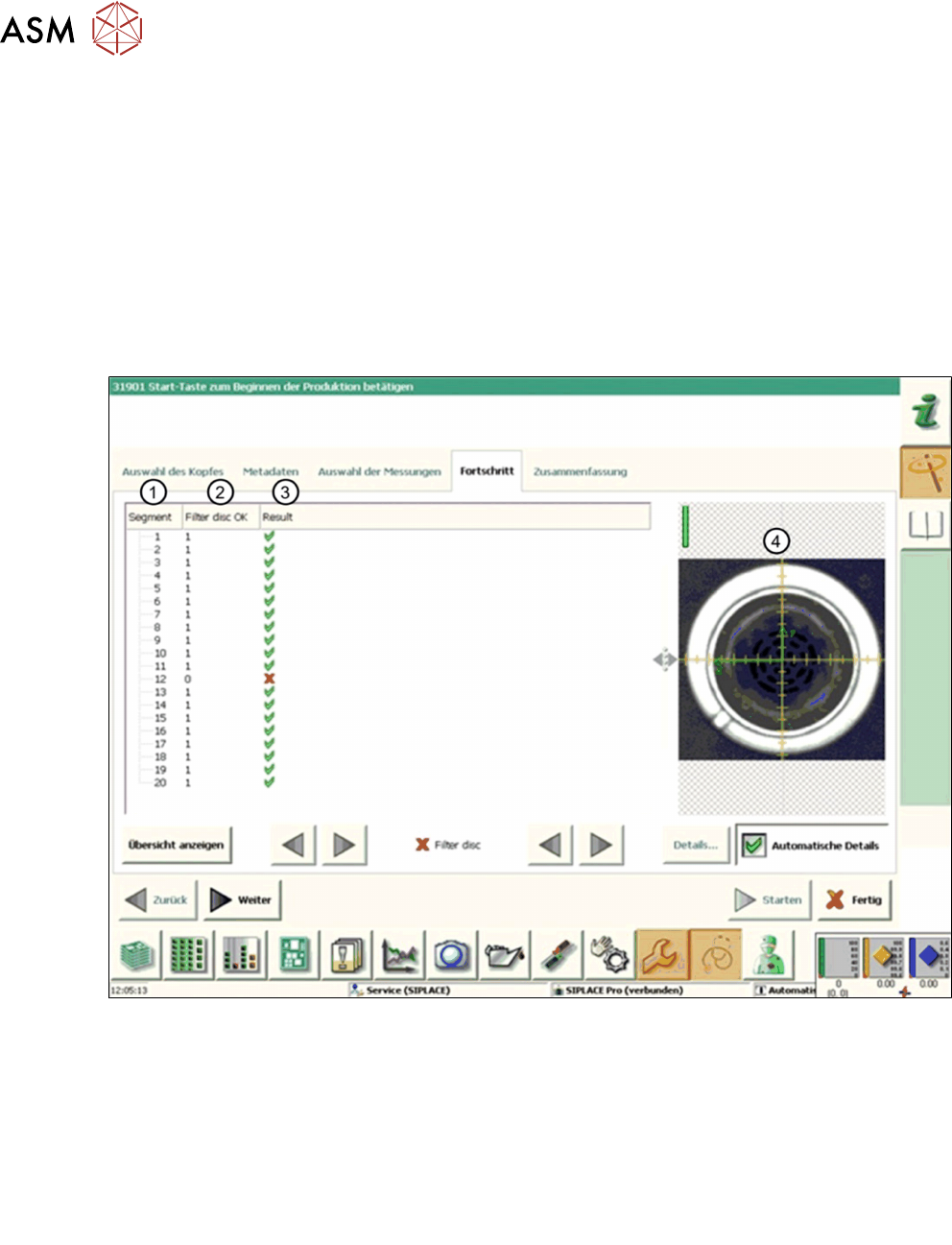
Fig.42: Result view – Filter disc
1 Measured Segment
2 Filter disc OK provides the status of the filter disk verification:
●
‘0’ indicates an error: The filter disc is either missing or the existing filter disc is pol-
luted.
●
‘1’ indicates that no pollution was detected on the filter disc
3 Result view indicating if the values are within (green tick) or outside (red cross) the limits.
4 Vision image showing the filter disk, captured by the component camera.
6 Description of the test results
6.10 Filter Disc
Software Manual SIPLACE Head Verification 03/2018 53
6.10.3 Interpretation of the results obtained
‘Filter disk OK’ error for all segments
Cause Solution
Holding circuit clogged ► Clean the holding circuit or replace it.
Filter disks clogged ► Replace the filter disks.
‘Filter disk OK’ error for individual segments
Cause Solution
Filter disks clogged ► Replace the filter disk.
6 Description of the test results
6.11 Force measurement for C&P heads
54 Software Manual SIPLACE Head Verification 03/2018
6.11 Force measurement for C&P heads
6.11.1 Measurement principle
During force measurement, the placement force is measured for each segment at an angle of 0°,
90°, 180° and 270°.
Depending on the head to be verified, the following force measurements are available:
●
Force LS (dynamic)
●
Force 01005 (dynamic)
●
Force 5N (dynamic)
●
Force 10N (dynamic)
6.11.2 Measurement result
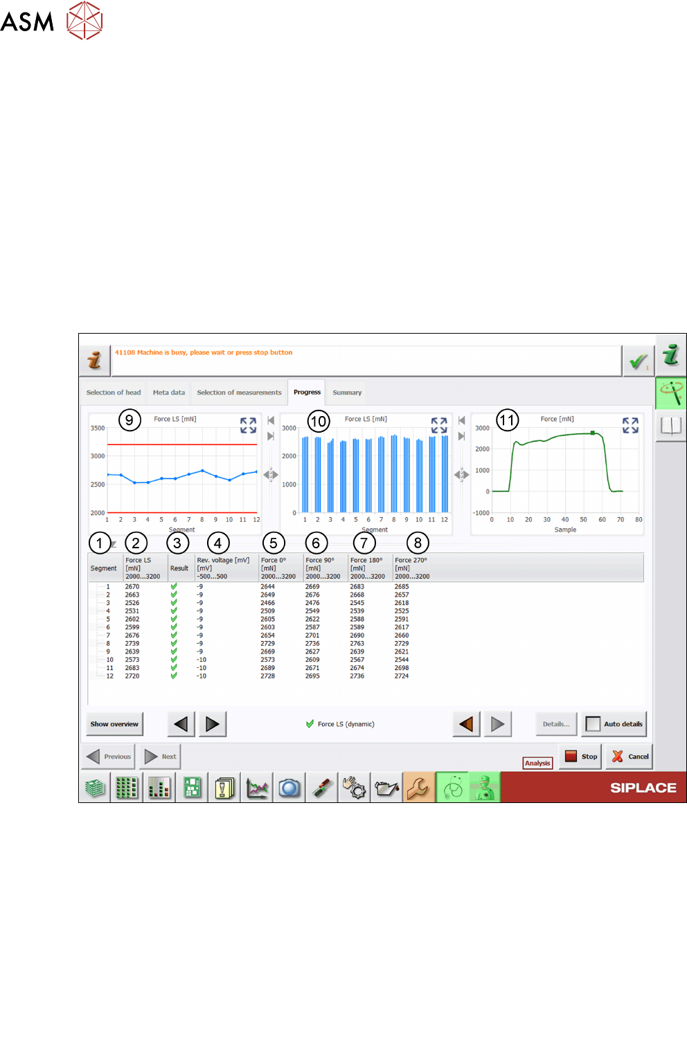
The following image shows an example of the ForceLS(dynamic) measurement:
Fig.43: Result view – Force LS (dynamic)
1 Measured Segment
2 The Force column shows the mean value of the forces measured at different angles:
Force
(n)
= Mean Force
(n0°, n90°, n180°, n270°)
3 Result view indicating if the values are within (green tick) or outside (red cross) the limits.
4 Values of the Rev. voltage measurement show the reference voltage during the measure-
ment.
Always check for a low reference voltage as otherwise this can limit the available measure-
ment range.
5 Values of the Force0° measurement
6 Values of the Force90° measurement