00197787-02_SI_SIPLACE_HeadVerification_EN.pdf - 第70页
6 Description of the test results 6.18 Nozzle spring 70 Software Manual SIPLACE Head Verification 03/2018 6.18 Nozzle spring 6.18.1 Measurement principle The Nozzle spring measurement checks the state of the spring with …
6 Description of the test results
6.17 Holding circuit (sealed nozzles)
Software Manual SIPLACE Head Verification 03/2018 69
6.17.3 Interpretation of the results obtained
‘Holding circuit (sealed nozzles)’ error for all segments
Cause Solution
Vacuum supply defective ► Check the air hoses.
► Check and maintain the vacuum pump if
applicable.
Vacuum block of CPP defective ► Replace the CPP vacuum block with a new
one.
Leaky O-ring between vacuum unit and silencer ► Check the O-ring assembly or replace it.
Seal for holding circuit / aperture ring incorrectly
fitted or damaged
► Check the seal position and replace it if
necessary.
‘Holding circuit (sealed nozzles)’ error for individual segments
Cause Solution
Filter disk damaged or incorrectly fitted ► Replace the filter disk with a new one.
Vacuum hose for segment damaged or dirty ► Clean the vacuum hose and replace it if
necessary.
Holding circuit unit polluted ► Clean the holding circuit unit in an ultra-
sonic bath.
Leaky vacuum nozzle ► Replace the vacuum nozzle with a new
one.
‘Holding circuit (sealed nozzles)’ error for more than one segment
Cause Solution
Holding circuit unit polluted ► Clean the holding circuit unit in an ultra-
sonic bath.
Seal for holding circuit / aperture ring incorrectly
fitted or damaged
► Check the seal position and replace it if
necessary.
6 Description of the test results
6.18 Nozzle spring
70 Software Manual SIPLACE Head Verification 03/2018
6.18 Nozzle spring
6.18.1 Measurement principle
The Nozzle spring measurement checks the state of the spring with respect to its deflection, brit-
tleness and the switching (signal) threshold at the Z-axis down light barrier.
Before the measurement starts, a head reference run is carried out during which all nozzles are
pressed onto the DP at the nozzle station to ensure a firm fitting. During the measurement itself,
every segment is moved down and back up again using different travel profiles to measure the pos-
itions at which the end signal is triggered.
●
The nozzle spring is verified by comparing the positions at which the end signal is triggered,
moving the segment down first with low force and the current sensor mode (Z-Low Force), fol-
lowed by high force and light barrier mode (Z-High Force).
●
The threshold value is verified by comparing the position at which the end signal is triggered,
moving the segment down with standard force and light barrier mode (Z-Light Barrier), with
the position determined for the low force movement (Z-Low Force).
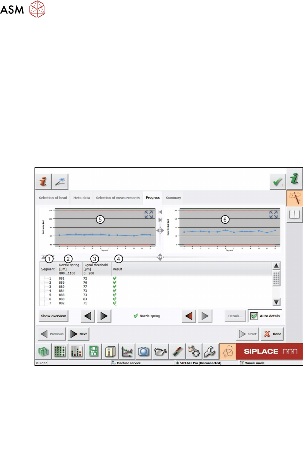
6.18.2 Measurement result
Fig.52: Result view – Nozzle spring measurement
1 Measured Segment
2 Calculated value for the spring that has been compressed completely:
Nozzlespring = Z-HighForce – Z-LowForce
3 Calculated value for the distance until the Z-axis down light barrier is triggered.
Signal threshold = Z-Light Barrier - Z-Low Force
4 Result view indicating if the values are within (green tick) or outside (red cross) the limits.
5 Graph showing the Nozzle spring values for each segment.
6 Graph showing the Signal threshold values for each segment.

6 Description of the test results
6.18 Nozzle spring
Software Manual SIPLACE Head Verification 03/2018 71
6.18.3 Interpretation of the results obtained
‘Nozzle spring’ / ‘Signal threshold’ error for all segments
Cause Solution
Light barrier Z-down defective ► Check the Z-axis down light barrier and re-
place it if necessary.
‘Nozzle spring’ / ‘Signal threshold’ error for individual segments
Cause Solution
Segment spring is bent or mechanically dam-
aged.
► Replace the DP.
The position, fixture or state of the cover switch-
ing ring is faulty.
► Check the fixture and, if necessary, re-
place the cover switching ring.
Spring pin at back of DP lock damaged. ► Replace the head.