00197787-02_SI_SIPLACE_HeadVerification_EN.pdf - 第74页
6 Description of the test results 6.19 Segment offset up & down (fast) 74 Software Manual SIPLACE Head Verification 03/2018 13 Table showing an overview of the largest and smallest value determined: ● UpX = UpX max…
6 Description of the test results
6.19 Segment offset up & down (fast)
Software Manual SIPLACE Head Verification 03/2018 73
6.19.2 Measurement result
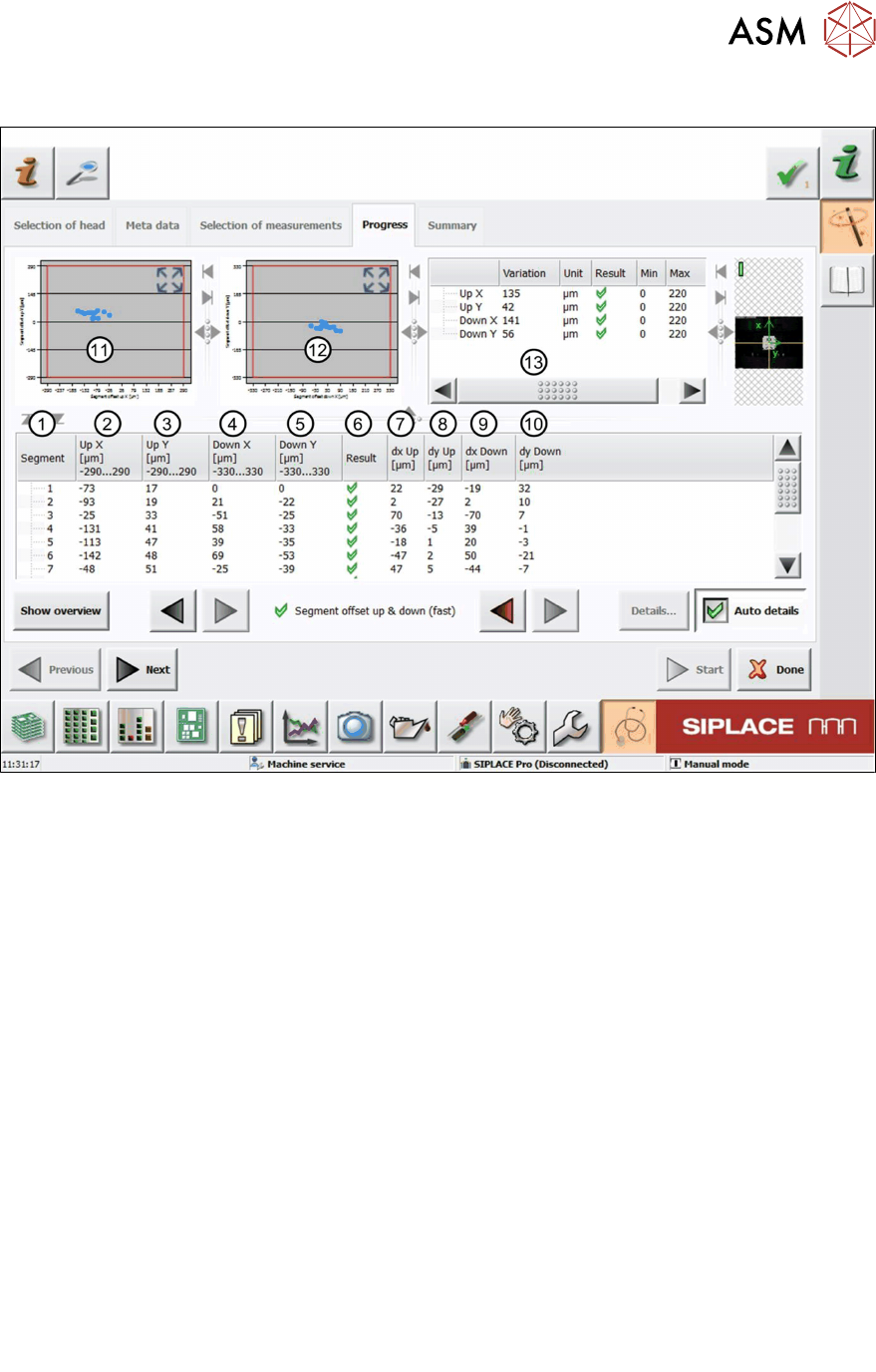
Fig.53: Result view – Segment offset up and down (fast)
1 Measured Segment
2 Calculated Segmentoffsetup value "UpX":
UpX
Segment (1)
is used as the reference to calculate the other segment offsets.
UpX
Segment (n)
= UpX
Segment (1)
+ dxUp
Segment (n)
– dxUp
Segment (1)
3 Calculated Segmentoffsetup value "UpY":
The calculation follows the same principle as for UpX.
4 Calculated Segmentoffsetdown value "DownX":
DownX
Segment (1)
= 0 and is used as the reference to calculate the other segment offsets:
DownX
Segment (n)
= dxDown
Segment (n)
– dxDown
Segment (1)
5 Calculated Segmentoffsetdown value "DownY":
The calculation follows the same principle as for DownX.
6 Result view indicating if the values are within (green tick) or outside (red cross) the limits.
7 Measured Segmentoffsetup value “dxUp”.
8 Measured Segmentoffsetup value “dyUp”.
9 Measured Segmentoffsetdown value “dxDown”.
10 Measured Segmentoffsetdown value “dyDown”.
11 Graph showing the calculated Segmentoffsetup values "Up X" and "Up Y".
12 Graph showing the calculated Segmentoffsetdown values "DownX" and "DownY".
6 Description of the test results
6.19 Segment offset up & down (fast)
74 Software Manual SIPLACE Head Verification 03/2018
13 Table showing an overview of the largest and smallest value determined:
●
UpX = UpX
max
– UPX
min
●
UpY = UpY
max
– UPY
min
●
DownX = DownX
max
– DownX
min
●
DownY = DownY
max
– DownY
min
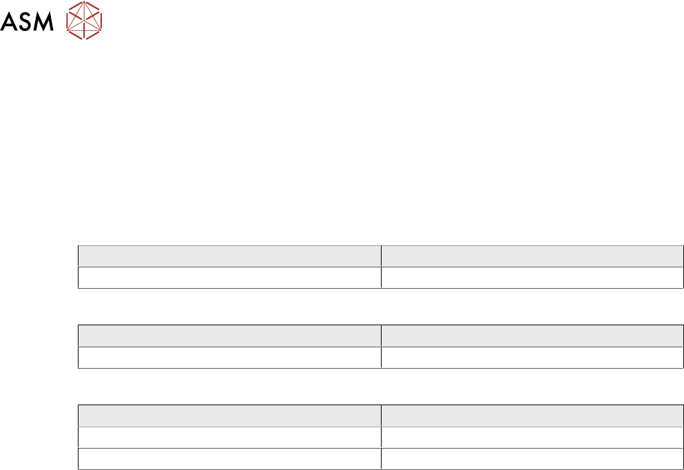
6.19.3 Interpretation of the results obtained
‘Up X’ and ‘Up Y’ error for all segments:
Cause Solution
Incorrect Zero point correction of the star. ► Check the zero point correction of the star.
‘Down X’ and ‘Down Y’ error for all segments:
Cause Solution
Linear bearing of the Z-axis loose or defective. ► Check / replace the Z-axis.
‘Up X’, ‘Up Y’, ‘Down X’ and ‘Down Y’ error for individual segments:
Cause Solution
Segment bent, possibly after crash. ► Replace the segment (DP).
Linear bearing of segment defective ► Replace the linear bearing (DP).
6 Description of the test results
6.20 Segment offset up & down
Software Manual SIPLACE Head Verification 03/2018 75
6.20 Segment offset up & down
6.20.1 Measurement principle
The Segment offset up & down measurement checks the degree to which a segment is outside
of its rotation axis. This eccentricity is also known as segment offset.
●
While "segment offset up" measures the rotation (offset) of the segment in the docked state
(Z-axis up), "segment offset down" measures the rotation of the segment in the bottom posi-
tion (Z-axis down).
●
The positions, therefore, illustrate the eccentricity of the segment axis in the pickup or place-
ment position, also referred to as offset between the component and PCB camera.
The measurement is performed for each segment in the top or bottom position at four angles (0°,
90°, 180° and 270°) to determine the exact rotation and to calculate the influence of the Z-axis lin-
ear guide between the segment top and segment bottom positions.
NOTICE
Segment no longer suitable for placement
The measurement is a prerequisite for the placement accuracy of the machine as the de-
termined values are used to calculate the actual placement position. The specified limits fol-
low the construction and production tolerances which can be compensated by the software.
If the segment offset exceeds the limits, the segment has most likely been deformed mech-
anically and is no longer suitable for accurate placement.
► Replace the segment before performing other measurements.
The measurement provides feedback about the following parts:
●
Deformed segments (DP / linear guide)
●
Defective Z-axis linear guides