00197787-02_SI_SIPLACE_HeadVerification_EN.pdf - 第76页
6 Description of the test results 6.20 Segment offset up & down 76 Software Manual SIPLACE Head Verification 03/2018 6.20.2 Measurement result Fig.54: Result view – Segment offset up & down 1 Measured Segment 2 …
6 Description of the test results
6.20 Segment offset up & down
Software Manual SIPLACE Head Verification 03/2018 75
6.20 Segment offset up & down
6.20.1 Measurement principle
The Segment offset up & down measurement checks the degree to which a segment is outside
of its rotation axis. This eccentricity is also known as segment offset.
●
While "segment offset up" measures the rotation (offset) of the segment in the docked state
(Z-axis up), "segment offset down" measures the rotation of the segment in the bottom posi-
tion (Z-axis down).
●
The positions, therefore, illustrate the eccentricity of the segment axis in the pickup or place-
ment position, also referred to as offset between the component and PCB camera.
The measurement is performed for each segment in the top or bottom position at four angles (0°,
90°, 180° and 270°) to determine the exact rotation and to calculate the influence of the Z-axis lin-
ear guide between the segment top and segment bottom positions.
NOTICE
Segment no longer suitable for placement
The measurement is a prerequisite for the placement accuracy of the machine as the de-
termined values are used to calculate the actual placement position. The specified limits fol-
low the construction and production tolerances which can be compensated by the software.
If the segment offset exceeds the limits, the segment has most likely been deformed mech-
anically and is no longer suitable for accurate placement.
► Replace the segment before performing other measurements.
The measurement provides feedback about the following parts:
●
Deformed segments (DP / linear guide)
●
Defective Z-axis linear guides
6 Description of the test results
6.20 Segment offset up & down
76 Software Manual SIPLACE Head Verification 03/2018
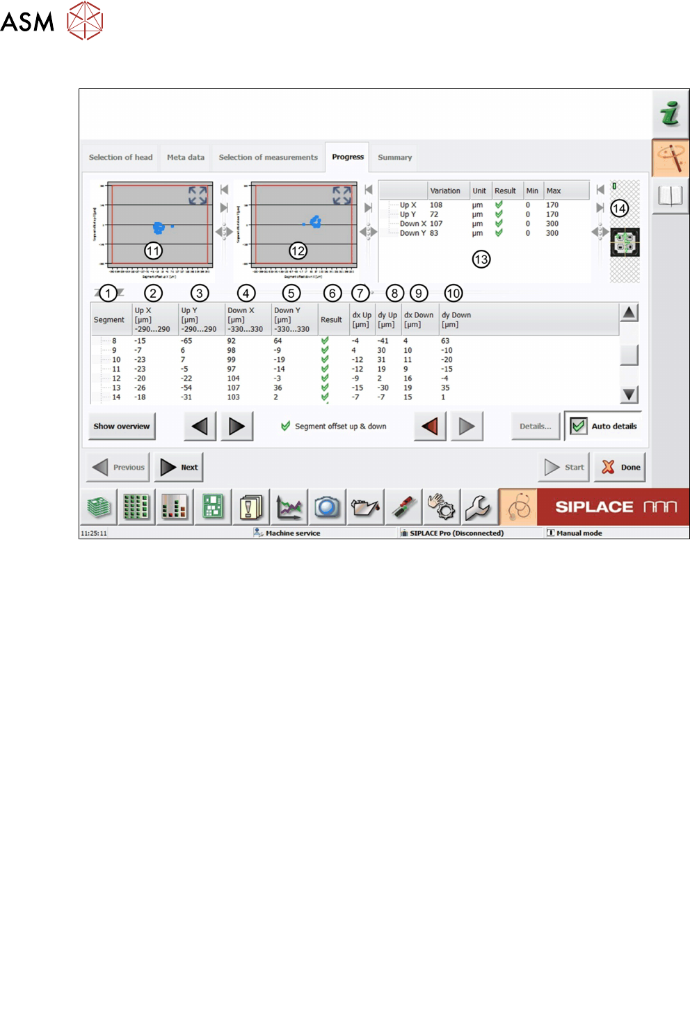
6.20.2 Measurement result
Fig.54: Result view – Segment offset up & down
1 Measured Segment
2 A different calculation of the segment offset UpX is used for segment 1 and all other seg-
ments.
For segment 1, UpX is calculated from the mean value of the measured Xoffsets (compo-
nent to PCB camera) at an angle of 0°, 90°, 180° and 270°, and the value dxUp:
UPX
Segment 1
= MeanOffsetX
0°, 90°, 180° and 270°
+ dxUp
Segment 1
For all other segments, UPX is calculated using segment 1 as a reference position:
UPX
Segment n
= UPX
Segment 1
- (dxUp
Segment 1
– dxUp
Segment n
)
3 The segment offset UpY is calculated following the same principle as for UpX:
UPY
Segment 1
= MeanOffsetY
0°, 90°, 180° and 270°
+ dyUp
Segment 1
UPY
Segment n
= UPY
Segment 1
- (dyUp
Segment 1
– dyUp
Segment n
)
4 The segment offset DownX is calculated following the same principle as for UpX:
DownX
Segment 1
= MeanOffsetX
0°, 90°, 180° and 270°
+ dxDown
Segment 1
DownX
Segment n
= DownX
Segment 1
- (dxDown
Segment 1
– dxDown
Segment n
)
5 The segment offset DownY is calculated following the same principle as for UpX:
DownY
Segment 1
= MeanOffsetY
0°, 90°, 180° and 270°
+ dyDown
Segment 1
DownY
Segment n
= DownY
Segment 1
- (dyDown
Segment 1
– dyDown
Segment n
)
6 Result view indicating if the values are within (green tick) or outside (red cross) the limits.
7 The segment offset dxUp is calculated from the mean value of the segment to the compo-
nent camera center at an angle of 0°, 90°, 180° and 270°.
8 The segment offset dyUp is calculated from the mean value of the segment to the compo-
nent camera center at an angle of 0°, 90°, 180° and 270°.
9 The segment offset dxDown is calculated from the mean value of the segment to the
component camera center at an angle of 0°, 90°, 180° and 270°.
6 Description of the test results
6.20 Segment offset up & down
Software Manual SIPLACE Head Verification 03/2018 77
10 The segment offset dyDown is calculated from the mean value of the segment to the
component camera center at an angle of 0°, 90°, 180° and 270°.
11 Graph showing the segment offset UpX (abscissas) and the segment offset UpY (ordin-
ate).
12 Graph showing the segment offset DownX (abscissas) and the segment offset DownY
(ordinate).
13 Additional parameters comparing the smallest and largest value determined.
●
Up X = UpXmax – UpXmin
●
Up Y = UpYmax – UpYmin
●
Down X = DownXmax – DownXmin
●
DownY = DownYmax – DownYmin
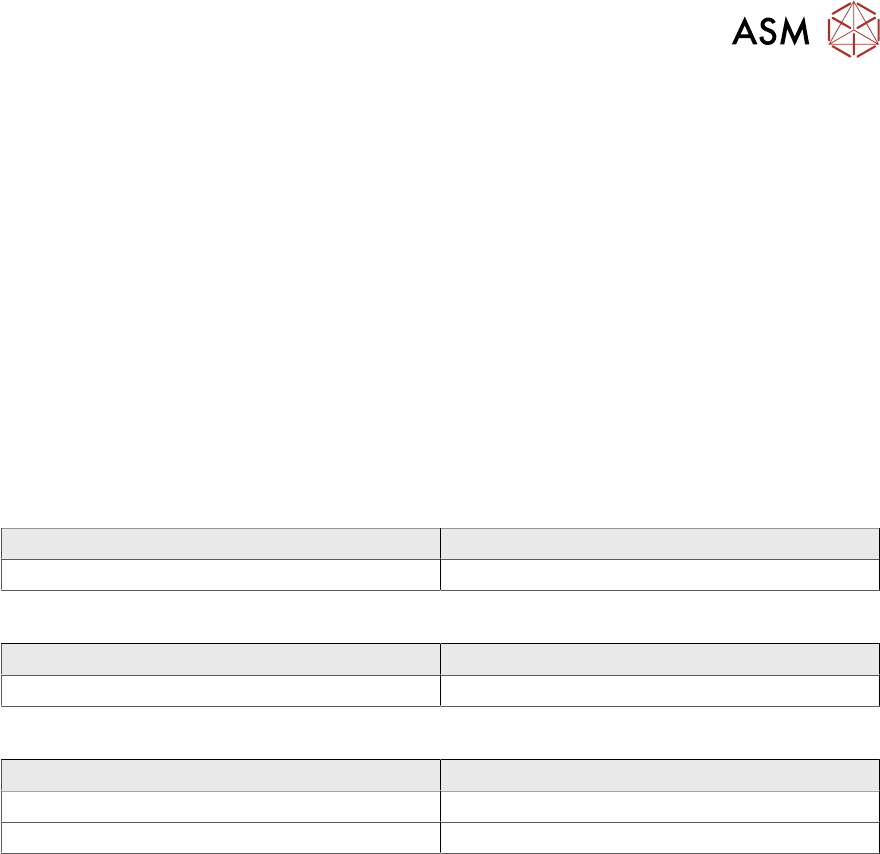
6.20.3 Interpretation of the results obtained
‘Up X’ and ‘Up Y’ error for all segments:
Cause Solution
Incorrect Zero point correction of the star. ► Check the zero point correction of the star.
‘Down X’ and ‘Down Y’ error for all segments:
Cause Solution
Linear bearing of the Z-axis loose or defective. ► Check / replace the Z-axis.
‘Up X’, ‘Up Y’, ‘Down X’ and ‘Down Y’ error for individual segments:
Cause Solution
Segment bent, possibly after crash. ► Replace the segment (DP).
Linear bearing of segment defective ► Replace the linear bearing (DP).