00197787-02_SI_SIPLACE_HeadVerification_EN.pdf - 第77页
6 Description of the test results 6.20 Segment offset up & down Software Manual SIPLACE Head Verification 03/2018 77 10 The segment offset dyDown is calculated from the mean value of the segment to the component cam…
6 Description of the test results
6.20 Segment offset up & down
76 Software Manual SIPLACE Head Verification 03/2018
6.20.2 Measurement result
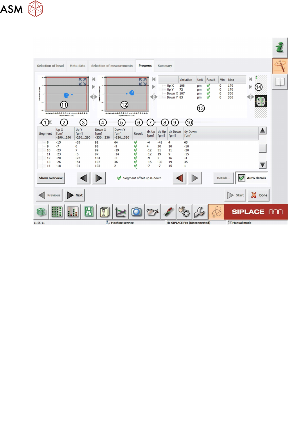
Fig.54: Result view – Segment offset up & down
1 Measured Segment
2 A different calculation of the segment offset UpX is used for segment 1 and all other seg-
ments.
For segment 1, UpX is calculated from the mean value of the measured Xoffsets (compo-
nent to PCB camera) at an angle of 0°, 90°, 180° and 270°, and the value dxUp:
UPX
Segment 1
= MeanOffsetX
0°, 90°, 180° and 270°
+ dxUp
Segment 1
For all other segments, UPX is calculated using segment 1 as a reference position:
UPX
Segment n
= UPX
Segment 1
- (dxUp
Segment 1
– dxUp
Segment n
)
3 The segment offset UpY is calculated following the same principle as for UpX:
UPY
Segment 1
= MeanOffsetY
0°, 90°, 180° and 270°
+ dyUp
Segment 1
UPY
Segment n
= UPY
Segment 1
- (dyUp
Segment 1
– dyUp
Segment n
)
4 The segment offset DownX is calculated following the same principle as for UpX:
DownX
Segment 1
= MeanOffsetX
0°, 90°, 180° and 270°
+ dxDown
Segment 1
DownX
Segment n
= DownX
Segment 1
- (dxDown
Segment 1
– dxDown
Segment n
)
5 The segment offset DownY is calculated following the same principle as for UpX:
DownY
Segment 1
= MeanOffsetY
0°, 90°, 180° and 270°
+ dyDown
Segment 1
DownY
Segment n
= DownY
Segment 1
- (dyDown
Segment 1
– dyDown
Segment n
)
6 Result view indicating if the values are within (green tick) or outside (red cross) the limits.
7 The segment offset dxUp is calculated from the mean value of the segment to the compo-
nent camera center at an angle of 0°, 90°, 180° and 270°.
8 The segment offset dyUp is calculated from the mean value of the segment to the compo-
nent camera center at an angle of 0°, 90°, 180° and 270°.
9 The segment offset dxDown is calculated from the mean value of the segment to the
component camera center at an angle of 0°, 90°, 180° and 270°.
6 Description of the test results
6.20 Segment offset up & down
Software Manual SIPLACE Head Verification 03/2018 77
10 The segment offset dyDown is calculated from the mean value of the segment to the
component camera center at an angle of 0°, 90°, 180° and 270°.
11 Graph showing the segment offset UpX (abscissas) and the segment offset UpY (ordin-
ate).
12 Graph showing the segment offset DownX (abscissas) and the segment offset DownY
(ordinate).
13 Additional parameters comparing the smallest and largest value determined.
●
Up X = UpXmax – UpXmin
●
Up Y = UpYmax – UpYmin
●
Down X = DownXmax – DownXmin
●
DownY = DownYmax – DownYmin
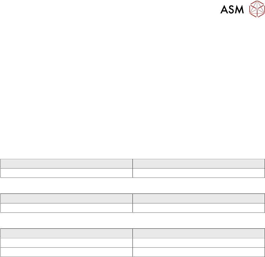
6.20.3 Interpretation of the results obtained
‘Up X’ and ‘Up Y’ error for all segments:
Cause Solution
Incorrect Zero point correction of the star. ► Check the zero point correction of the star.
‘Down X’ and ‘Down Y’ error for all segments:
Cause Solution
Linear bearing of the Z-axis loose or defective. ► Check / replace the Z-axis.
‘Up X’, ‘Up Y’, ‘Down X’ and ‘Down Y’ error for individual segments:
Cause Solution
Segment bent, possibly after crash. ► Replace the segment (DP).
Linear bearing of segment defective ► Replace the linear bearing (DP).
6 Description of the test results
6.21 Segment offset up (SOO)
78 Software Manual SIPLACE Head Verification 03/2018
6.21 Segment offset up (SOO)
6.21.1 Measurement principle
The Segment offset up measurement checks the degree to which a segment is outside of its rota-
tion axis in the top position. This eccentricity is also known as segment offset up.
Segment offset up is the offset of the segment center in the up position to the center of the
component camera.
The measurement is performed for each segment in the top position at four angles (0°, 90°, 180°
and 270°) to determine the exact rotation and to calculate the influence of the segment / Z-axis lin-
earity.
NOTICE
Segment offset down not available at the HCS
The Segment offset down measurement requires a stationary camera which is not available
at the HCS. Therefore, this test is only available with the online verification.
NOTICE
Termination of test sequence
If a measurement shows a segment outside the allowed limits, all subsequent measure-
ments will be terminated. It is assumed that the segment is seriously deformed and that the
head is no longer able to perform.
► Replace the segment immediately before performing other measurements.