00197787-02_SI_SIPLACE_HeadVerification_EN.pdf - 第85页
6 Description of the test results 6.24 ZDS sensor values Software Manual SIPLACE Head Verification 03/2018 85 5 Value of the Springresp. low measurement. 6 Value of the Springresp.high measurement. 7 Value of the Ra…
6 Description of the test results
6.24 ZDS sensor values
84 Software Manual SIPLACE Head Verification 03/2018
6.24 ZDS sensor values
6.24.1 Measurement principle
The ZDS sensor values measurement determines the functionality of the Z-down light barrier and
the component sensor, in accordance with the rotary angles of the DP or segment.
Firstly, the reference run is applied to determine the brightness adjustment for the Z-down light bar-
rier (LED Gain). In relation to this, the voltage value is determined for the Z-down light barrier,
which provides a reference value (sensor value [mV]) for the distance to the switching ring.
Additional measurements are performed to determine the Z-down light barrier voltage values when
the switching ring issues the Z axis end position signal during placement (spring resp. low [mV])
and also when the Z axis makes contact at full force (spring resp. high [mV]), corresponding to a
complete compression of the segment spring.
In further tests, the rotary axis of the DP / segment is rotated by a full rotation (360°) while the Z-
down light barrier voltage values are constantly recorded and an image of the distance from the Z-
down light barrier to the switching ring is recorded as well. The changes in voltage are measured in
steps of 5°, to prove a relatively even fluctuation. The entire change in voltage is also determined
over the complete 360°.
As this measurement is performed in the component sensor area, the changes in nozzle tip length
can be measured across the entire 360°. These changes in length are recorded in steps of 5° and
must remain within a certain range.
6.24.2 Measurement result
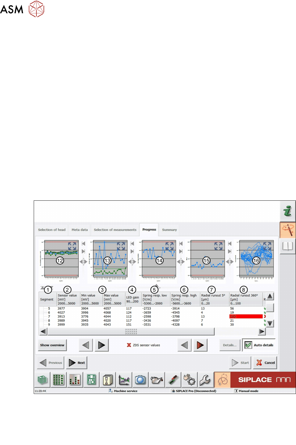
Fig.58: Result view – ZDS sensor values 1/2
1 Measured Segment
2 The Sensorvalue is the mean value of the Minvalue and Maxvalue measurement.
3 Values of the Minvalue and Maxvalue measurement.
4 Value of the LEDgain measurement.
6 Description of the test results
6.24 ZDS sensor values
Software Manual SIPLACE Head Verification 03/2018 85
5 Value of the Springresp.low measurement.
6 Value of the Springresp.high measurement.
7 Value of the Radialrunout5° measurement.
8 Value of the Radialrunout360° measurement.
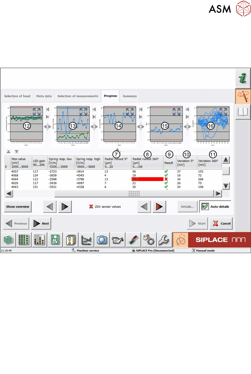
Fig.59: Result view – ZDS sensor values 2/2
7 Value of the Radialrunout5° measurement.
8 Value of the Radialrunout360° measurement.
9 Result view indicating if the values are within (green tick) or outside (red cross) the limits.
10 Value of the Variation5° measurement.
11 Value of the Variation360° measurement.
12 Graph showing the Sensormean (blue), Min (green) and Max (green) values for each
segment.
13 Graph showing the Radialrunout5° (green) and Radialrunout360° (blue) values for
each segment.
14 Graph showing the Springresp.low values for each segment.
15 Graph showing the LEDgain values for each segment.
16 Graph showing the Sensorvaluevariation values for each segment.
6 Description of the test results
6.24 ZDS sensor values
86 Software Manual SIPLACE Head Verification 03/2018
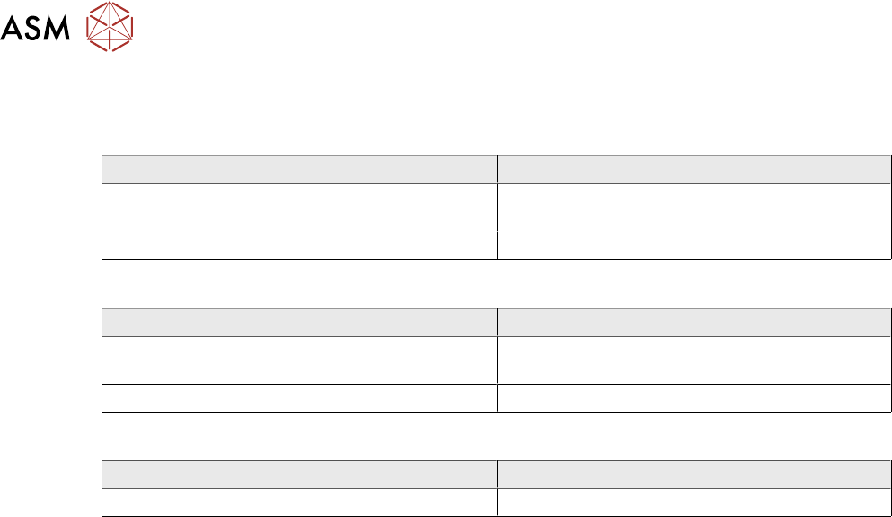
6.24.3 Interpretation of the results obtained
‘Max value’ or ‘LED gain’ error for all segments
Cause Solution
Z-axis down light barrier polluted ► Clean the light barrier using a cleaning
stick and isopropanol.
Surface of Z-axis down light barrier damaged ► Replace the light barrier.
‘Max value’ or ‘LED gain’ error for individual segments
Cause Solution
Switch ring polluted ► Clean the switch ring using a cleaning stick
and isopropanol.
Surface of switch ring damaged ► Replace the respective DP.
‘Radial runout 5° / 360°’ or ‘Variation 5° / 360°’ error for individual segments
Cause Solution
Segment bent, e.g. due to head crash ► Replace the DP.