00197787-02_SI_SIPLACE_HeadVerification_EN.pdf - 第86页
6 Description of the test results 6.24 ZDS sensor values 86 Software Manual SIPLACE Head Verification 03/2018 6.24.3 Interpretation of the results obtained ‘Max value’ or ‘LED gain’ error for all segments Cause Solution …
6 Description of the test results
6.24 ZDS sensor values
Software Manual SIPLACE Head Verification 03/2018 85
5 Value of the Springresp.low measurement.
6 Value of the Springresp.high measurement.
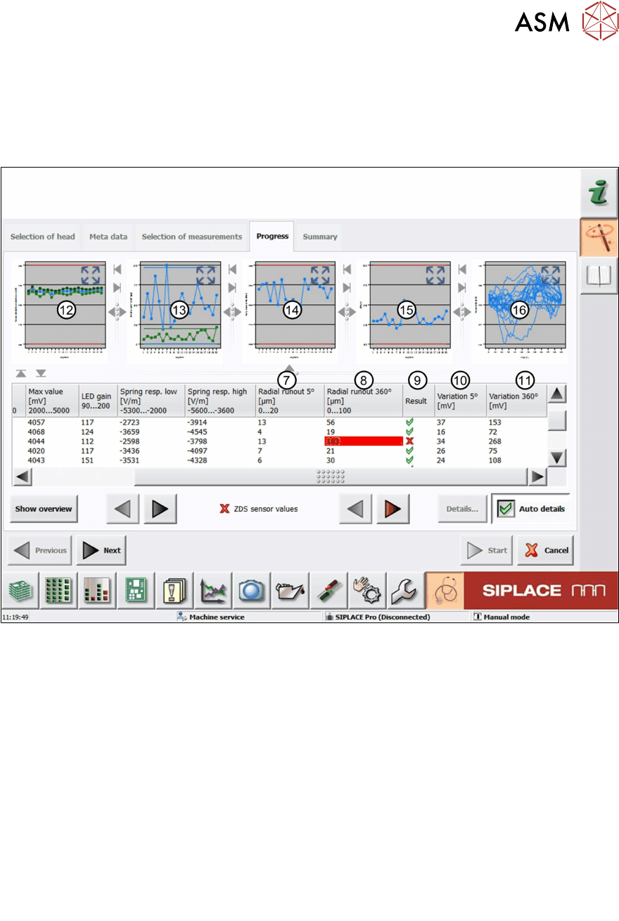
7 Value of the Radialrunout5° measurement.
8 Value of the Radialrunout360° measurement.
Fig.59: Result view – ZDS sensor values 2/2
7 Value of the Radialrunout5° measurement.
8 Value of the Radialrunout360° measurement.
9 Result view indicating if the values are within (green tick) or outside (red cross) the limits.
10 Value of the Variation5° measurement.
11 Value of the Variation360° measurement.
12 Graph showing the Sensormean (blue), Min (green) and Max (green) values for each
segment.
13 Graph showing the Radialrunout5° (green) and Radialrunout360° (blue) values for
each segment.
14 Graph showing the Springresp.low values for each segment.
15 Graph showing the LEDgain values for each segment.
16 Graph showing the Sensorvaluevariation values for each segment.

6 Description of the test results
6.24 ZDS sensor values
86 Software Manual SIPLACE Head Verification 03/2018
6.24.3 Interpretation of the results obtained
‘Max value’ or ‘LED gain’ error for all segments
Cause Solution
Z-axis down light barrier polluted ► Clean the light barrier using a cleaning
stick and isopropanol.
Surface of Z-axis down light barrier damaged ► Replace the light barrier.
‘Max value’ or ‘LED gain’ error for individual segments
Cause Solution
Switch ring polluted ► Clean the switch ring using a cleaning stick
and isopropanol.
Surface of switch ring damaged ► Replace the respective DP.
‘Radial runout 5° / 360°’ or ‘Variation 5° / 360°’ error for individual segments
Cause Solution
Segment bent, e.g. due to head crash ► Replace the DP.
6 Description of the test results
6.25 Z positioning time
Software Manual SIPLACE Head Verification 03/2018 87
6.25 Z positioning time
6.25.1 Measurement principle
The Z positioning time measurement checks the consistency of the Z-axis positioning and indic-
ates the condition of the Z-axis drive and linear guide.
●
The Z-axis is positioned up and down to the exact same position 20 times. For each position-
ing action, the time is determined it took the Z-axis to reach the position. If the Z-axis moves
easily to the position, the Z-axis drive and linear guide are in good condition.
●
If the Z-axis is not moving smoothly, a mechanical problem exists.
6.25.2 Measurement result
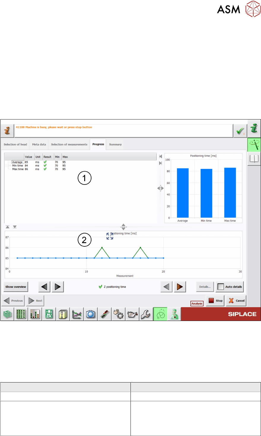
Fig.60: Result view – Z positioning time
1 Minimum, maximum and average time determined to reach the target position.
2 Graph showing the Z-axis positioning time.
6.25.3 Interpretation of the results obtained
‘Z positioning time’ error
Cause Solution
Blockage at the Z-axis linear bearing ► Check / maintain the linear bearing.
Z-axis drive and/or linear bearing defective ► Check / maintain the linear bearing.
► Replace the P&P module.
► Send the P&P module to ASM for cus-
tomer specific repair.