TR5DNR_TR5DNX-Rev04.pdf
Matrix T ray Server TR5DNR TR5DNX Re v . 04 1.As to"#01 "and"# 02"ref ertot he"Note "g i ve natt hetopo fth e respecti vepag es. 2.C odeson the" Qty"colu mn …
Matrix Tray Server
TR5DNR
TR5DNX
Rev.04
1.Asto"#01"and"#02"refertothe"Note"givenatthetopoftherespectivepages.
2.Codesonthe"Qty"column
・ Eachnumeralindicatesthenumberofpartsrequired.
・ "0.1"and"2.5"indicatethelength(inmeters)oftherespectiveparts.
3.Parenthesesmeanthatthecorrespondingpartisasubpartthatconstructsanassemblypart.
4.DottedlinesontheFiguresindicateassemblyparts.
1. リ ス ト ページの #01、 #02 等の印は、 ページ上の " 注記 " の説明を ご参照下 さ い。
2. 数量欄の数字は、 個数を表 し 、 0.1、 2.5 等の数値は、 長 さ (単位 メ ー ト ル) を表 し ます。
3. 数量欄の ( ) は、 組部品を構成 し てい る子部品であ る こ と を 意味 し ます。
4. イ ラ ス ト ページの-----枠は、 組構成であ る こ と を意味 し ます。
CONTENTS
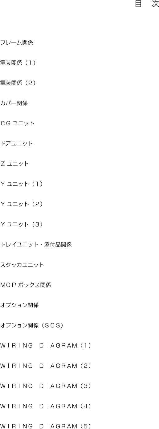
1. FRAME COMPONENTS .....................................................................................................................................................1
2. ELECTRIC APPARATUS COMPONENTS (1).................................................................................................................... 3
3. ELECTRIC APPARATUS COMPONENTS (2).................................................................................................................... 5
4. COVER COMPONENTS.....................................................................................................................................................7
5. CG UNIT..............................................................................................................................................................................9
6. DOOR UNIT ...................................................................................................................................................................... 11
7. Z UNIT............................................................................................................................................................................... 13
8. Y UNIT (1) ......................................................................................................................................................................... 15
9. Y UNIT (2) ......................................................................................................................................................................... 17
10. Y UNIT (3) ....................................................................................................................................................................... 19
11. TRAY UNIT & APPEND PARTS COMPONENTS .......................................................................................................... 21
12. STACKER UNIT .............................................................................................................................................................. 23
13. MOP BOX COMPONENTS............................................................................................................................................. 25
14. OPTIONAL COMPONENTS ...........................................................................................................................................27
15. OPTIONAL COMPONENTS (SCS)................................................................................................................................. 29
16. WIRING DIAGRAM (1).................................................................................................................................................... 31
17. WIRING DIAGRAM (2).................................................................................................................................................... 33
18. WIRING DIAGRAM (3).................................................................................................................................................... 35
19. WIRING DIAGRAM (4).................................................................................................................................................... 37
20. WIRING DIAGRAM (5).................................................................................................................................................... 39
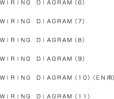
21. WIRING DIAGRAM (6).................................................................................................................................................... 41
22. WIRING DIAGRAM (7).................................................................................................................................................... 43
23. WIRING DIAGRAM (8).................................................................................................................................................... 45
24. WIRING DIAGRAM (9).................................................................................................................................................... 47
25. WIRING DIAGRAM (10)(FOR EN)..................................................................................................................................49
26. WIRING DIAGRAM (11)..................................................................................................................................................51