Technical_reference - 第107页
Technical Service Manual 107 Revision Dat e: August 2004 INDIVIDUAL CELL SENSING Individual Cell Sensing and A larm is: ! Standard, (installed on all ovens ) ) A n option, (NOT installed on all ovens) DESCRIPTION: The In…
Technical Service Manual 106 Revision Date: August 2004
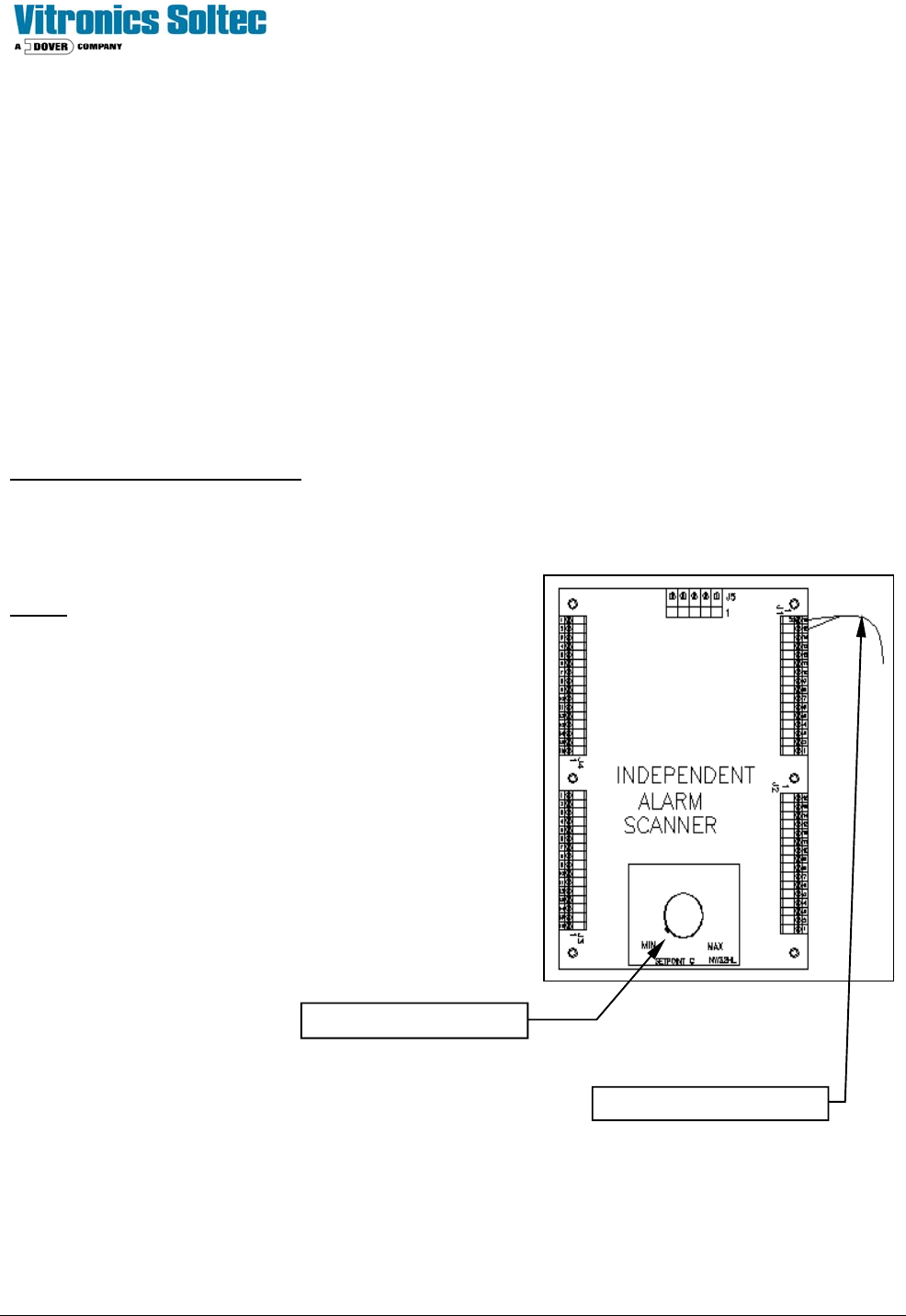
INDEPENDENT ALARM SCANNER OVER-TEMP & ALARM/SHUTDOWN
The Independent Alarm Scanner is:
! Standard, (installed on all ovens) ) An option, (NOT installed on all ovens)
DESCRIPTION:
The Independent Alarm Scanner & Alarm/Shutdown (IAS) system provides a redundant temperature backup system in
the event that a heating cell exceeds the critical temperature safety limit. The hardware consists of one (1) additional
thermocouple per heat cell, and the Independent Alarm Scanner (IAS) instrument, which can monitor as many as 32
thermocouples.
A second type K thermocouple is clamped on the face of every addition to the standard T/C
The Independent Alarm Scanner (IAS) receives each of these thermocouple signals as separate inputs and scans them
for an over-temperature indication.
The control circuit inter-action is:
In the event that an alarm condition (generated from the Redundant T/Cs) occurs, the IAS' alarm contact interrupts the 24
VAC to relay K4. This in interrupts the 120 VAC to the coil of heater contactor K2, and supplies an alarm signal to the
controller. The IAS unit scans all redundant thermocouples wired to it for an “Over-temperature” condition.
Notes:
Þ All unused T/C terminals MUST be jumpered.
Þ In case of a nuisance trip, the defective T/C can be found by
placing a jumper on the T/Cs one-at-a-time until the “alarm” is
eliminated.
Þ The setpoint should be set slightly higher than the temperature
expected during “normal oven operation”.
Þ The IAS will go into an alarm state in case of an IAS failure or
loss of power. A jumper on the output contacts will allow the
oven to be operated without the IAS until a replacement can be
installed.
Alarm setpoint adjustment
Thermocouple conductors

Technical Service Manual 107 Revision Date: August 2004
INDIVIDUAL CELL SENSING
Individual Cell Sensing and Alarm is:
! Standard, (installed on all ovens) ) An option, (NOT installed on all ovens)
DESCRIPTION:
The Individual Cell Sensing Option monitors for a cell fan motor failure or a heating cell over-temperature switch failure.
Each Cell Fan Motor has a speed sensor mounted on the end of the motor shaft. When a motor slows to less than 500
RPM, the sensor sends a signal to produce the Fan Low Alarm. . When a low fan speed warning exists, an alarm
message indicating the specific failed fan motor is displayed in the oven software. (Check the heat slinger on the suspect
motor to determine actual fan operation.)
Each heating cell is equipped with a bimetallic over-temperature switch mounted on the backside of the heater panel.
When the cell temperature exceeds the switch temperature, the internal contacts open. This will interrupt the 3- phase
power to the heaters, and a signal is sent to the Oven Controller to indicate an "over-temperature" condition. This will
generate an IAS alert alarm message along with an alarm message that corresponds to the cell location that generated
the alarm.
General
Cell sensor monitoring only takes place when the cell fans are running to avoid nuisance alarms due to the limitations of
the existing controller. The IAS alarm level setting must be set for an alarm level other then critical in order to sense and
report individual temperature switch alarms. This is because a critical alarm level setting will cause the cell fans to shut off
immediately when an alarm occurs with a critical alarm level setting.
Cell Motor sensors
Disconnect the following cell motor sensors one at time by unplugging connector P2 (1479503 3 position connector) on
the corresponding 3152701 cell interface board with the cell fans running above 100 rpm.
Install a 3-pin connector (1479503) with a jumper installed between pin 2 and pin 3 of the connector in place of the cell
motor sensor to force a cell fan alarm.
Verify that each alarm message is displayed on the PC and that the alarm message text corresponds to the cell location
with the alarm. It takes up to 68 seconds for an alarm condition to be detected and reported on the PC.
This test verifies that each 3152202 board is configured correctly and is communicating correctly with the DI board.
3152202
Board#
Model 520 Model 730/820 Model
940/1030
Model 1240
Master Zone 1 Top Zone 1 Top Zone 1 Top Zone 1 Top
Board 2 Zone 1 Bottom Zone 1 Bottom Zone 1 Bottom Zone 1 Bottom
Board 3 Zone 10 Top Zone 13 Top Zone 16 Top
Board 4 Zone 10
Bottom
Zone 13
Bottom
Zone 16
Bottom
Technical Service Manual 108 Revision Date: August 2004
CELL OVER TEMPERATURE SWITCHES
Preliminary Testing
Verify continuity of the heater over temperature switch circuit from wire number 2400 on zone 1 top to the coil of K4 on
the back panel.
Verify that the harness wiring is correct on connector P3 (1479508 8 position connector) of each 3152701 cell interface
board by unplugging the heater over temperature switch connector P1 (1479502 2 position connector) on each cell
interface board.
The red led on each cell interface board will light when the heater over temperature switch connector is unplugged to the
board. If the red led fails to light and continuity is OK in the heater over temperature switch circuit then the wires are
reversed in position 1 and 2 of connector P3.
Alarm Testing
Disconnect the following heater over temperature switches one at time by unplugging connector P1 (1479502 2 position
connector) on the corresponding 3152701 cell interface board.
Verify that each alarm message is displayed on the PC and that the alarm message text corresponds to the cell location
that has the alarm. It takes up to 68 seconds for an alarm condition to be detected and reported on the PC.
Verify that an IAS alert alarm message is present, which indicates that K4 on the back panel is shutting off when a heater
over temperature switch is opened.
This test verifies that each 3152202 board is configured correctly and is also communicating correctly with the DI board
and that relay K4 on the back panel shuts off when a heater over temperature switch is opened.
3152202
Board#
Model 520 Model 730/820 Model
940/1030
Model 1240
Master Zone 1 Top Zone 1 Top Zone 1 Top Zone 1 Top
Board 2 Zone 1 Bottom Zone 1 Bottom Zone 1 Bottom Zone 1 Bottom
Board 3 Zone 7 Top Zone 9 Top Zone 12 Top
Board 4 Zone 7 Bottom Zone 9 Bottom Zone 12
Bottom
3152202 Assembly 16 Channel Input Board Theory of Operation
The Atmel Atmega8 micro-controller is the main component on the board. The Atmega8 has one built in UART. The
UART is used to communicate to an RS485 connection on a multi-drop network through MODBUS protocol.
The RS485 port is not used directly with the existing controller since the existing controller does not have additional serial
ports available. Instead a frequency generator output from the micro-controller is used on the controller that is set as the
Master through switch 4 of dip switch S1 to communicate digital input status data to the existing controller through using a
counter input on the existing controller. The frequency generator output is derived by using the timer/counter compare
output of timer 1 of the Atmega8 micro-controller.