Technical_reference - 第110页
Technical Service Manual 110 Revision Dat e: August 2004 HEATER CELL O VER-TEMPERAT URE SW ITCHES Heater cell over- tem perature switches are: ) Standard, (installed on all ovens ) ! An option, (NOT installed on all oven…
Technical Service Manual 109 Revision Date: August 2004
The master controller initiates MODBUS commands to up to three other 3152202 boards connected on a RS485 network
to gather digital input status information from each board. The master controller transfers digital input status information
for itself and for up to three other 3152202 boards using a digital input handshake with the existing controller. The
frequency generator output transfers digital input status data as one nibble at a time (4 bits) to a counter input on the
existing controller. There is a special frequency output setting that serves as an identity stamp to mark the very first nibble
of the possible 16 nibbles that are sent. The existing controller momentarily sets a digital output that is connected to a
digital input on the 3152202 board serving as a Master. This is to signal that a frequency has been read correctly and to
prompt the Master to send the data for the next nibble or the identity stamp depending on where the Master controller is in
the send sequence. The existing controller checks the counter input once a second and signals the Master to send data
for the next nibble when the past and current counter values are equal, which is typically 4 seconds. It takes 68 seconds
to transfer all of the digital input status information for four 3152202 boards.
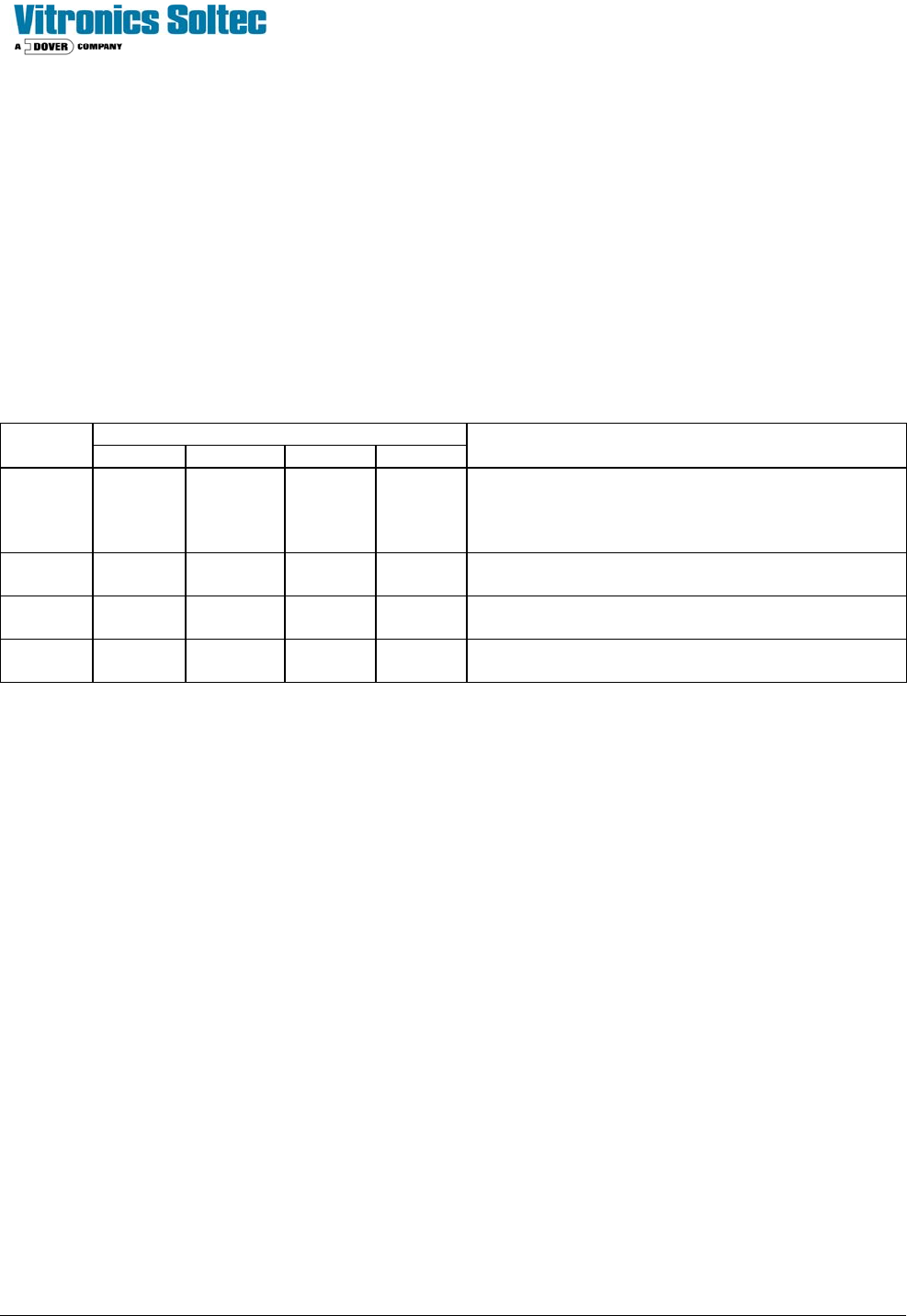
Table 1.0
S1 Dip Switch Settings
Board
Switch 1 Switch 2 Switch 3 Switch 4
Description
Master OFF OFF OFF ON
Board address offset 0, board functions as a
master on a MODBUS network and initiates
MODBUS commands to other boards on the
network
Board 2 ON OFF OFF OFF
Board address offset 1, board functions as a slave
on a MODBUS network
Board 3 OFF ON OFF OFF
Board address offset 2, board functions as a slave
on a MODBUS network
Board 4 ON ON OFF OFF
Board address offset 3, board functions as a slave
on a MODBUS network
Technical Service Manual 110 Revision Date: August 2004
HEATER CELL OVER-TEMPERATURE SWITCHES
Heater cell over-temperature switches are:
) Standard, (installed on all ovens) ! An option, (NOT installed on all ovens)
DESECRIPTION:
Each heating cell is equipped with a bimetallic over-temperature switch mounted on the backside of the heater panel.
When the cell temperature exceeds the switch temperature, the internal contacts open. This will interrupt the 3- phase
power to the heaters, and a signal is sent to the Oven Controller indicating an "over-temperature" condition. This will
generate an IAS alert alarm message.
This system generates only an IAS alert alarm message and will not indicate the cell location that generated the alarm.
The faulty cell must be found by diagnostically testing the functions of the cell over-temperature switches, looking for
either continuity (machine power removed) or voltage loss across the switch.
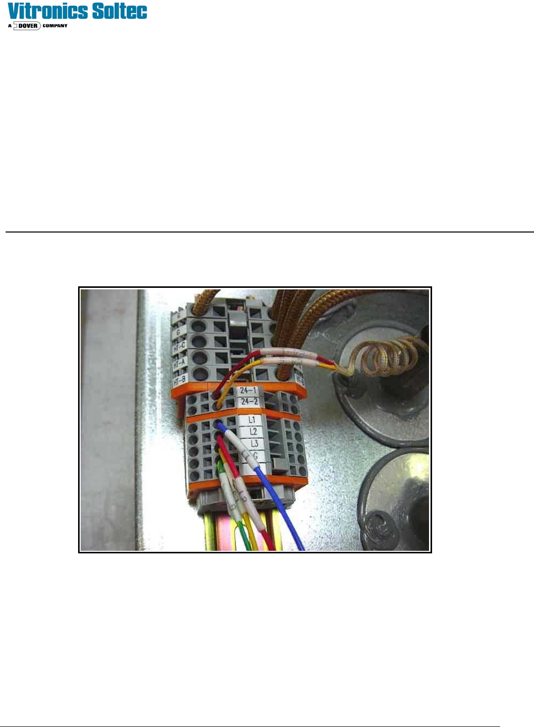
On the back (top / bottom side) of each heater cell is a terminal block assembly.
Check for either continuity or +24 VDC between terminals 24-1 and 24-2. To read continuity machine power must be
completely disconnected.
To read voltage place the positive lead in terminal 24-1 and the negative lead in ground to verify input voltage to the
switch. If input voltage is present, then move the positive lead to terminal 24-2. If there is no voltage present, the switch
is open. If the switch continuity or voltage checks are good, then move on to the next switch. Is it easiest to start at the
last heat zone on the top and then divide the machine in half for each subsequent check. If the last top heat zone switch
checks good, move directly to the bottom heat cells.
Technical Service Manual 111 Revision Date: August 2004
LIGHT TOWER
The Light Tower is:
! Standard, (installed on all ovens) ) An option, (NOT installed on all ovens)
DESCRIPTION:
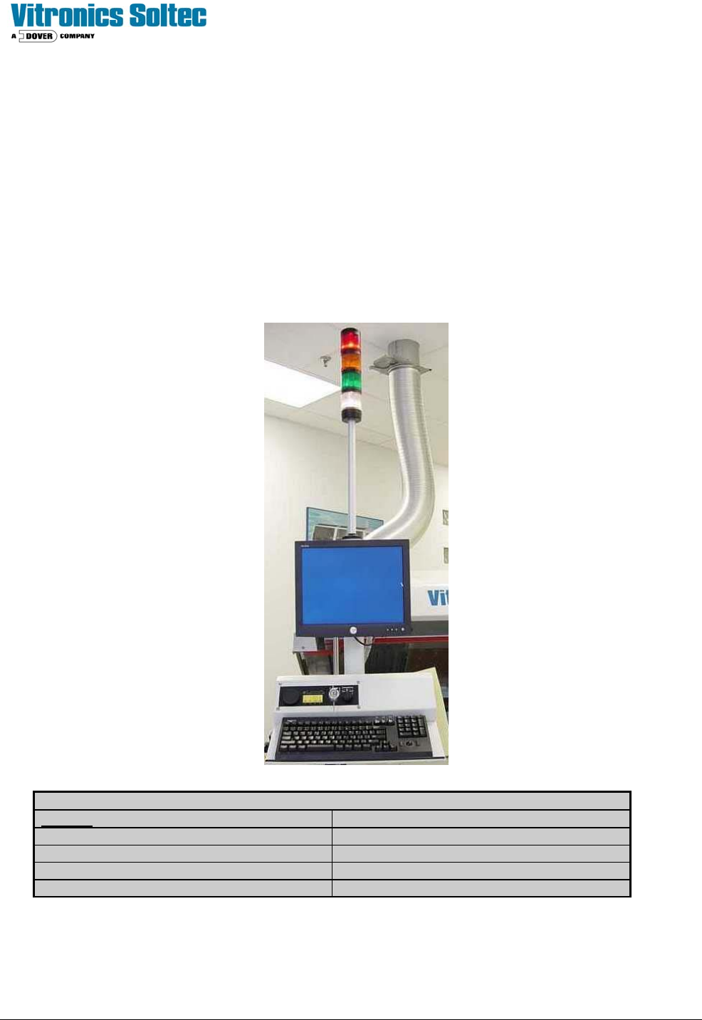
The Light Tower assembly is a mast with four indicating lights mounted on the on-load end of the Reflow Oven. The
lights indicate the status of Oven operation and are duplicates of functions and colors displayed by the Oven Control
Software on the computer screen.
The standard color arrangement is shown below.
(Other configurations are available by special order)
.
LIGHT TOWER LENS COLOR MEANING
COLOR
DESCRIPTION
RED Alarm and Shutdown
WHITE Power “On” / Applied to oven
AMBER Process Warning
GREEN Process Operation Ready (O.K.)
(Refer to Oven schematics for Light Tower and Alarm wiring)