Technical_reference - 第111页
Technical Service Manual 111 Revision Dat e: August 2004 LI GH T TOW ER The Light T ower is: ! Standard, ( installed on all ovens) ) An option, (NO T ins talled on all ovens) DESCRIPTION: The Light T ower assem bly is a …
Technical Service Manual 110 Revision Date: August 2004
HEATER CELL OVER-TEMPERATURE SWITCHES
Heater cell over-temperature switches are:
) Standard, (installed on all ovens) ! An option, (NOT installed on all ovens)
DESECRIPTION:
Each heating cell is equipped with a bimetallic over-temperature switch mounted on the backside of the heater panel.
When the cell temperature exceeds the switch temperature, the internal contacts open. This will interrupt the 3- phase
power to the heaters, and a signal is sent to the Oven Controller indicating an "over-temperature" condition. This will
generate an IAS alert alarm message.
This system generates only an IAS alert alarm message and will not indicate the cell location that generated the alarm.
The faulty cell must be found by diagnostically testing the functions of the cell over-temperature switches, looking for
either continuity (machine power removed) or voltage loss across the switch.
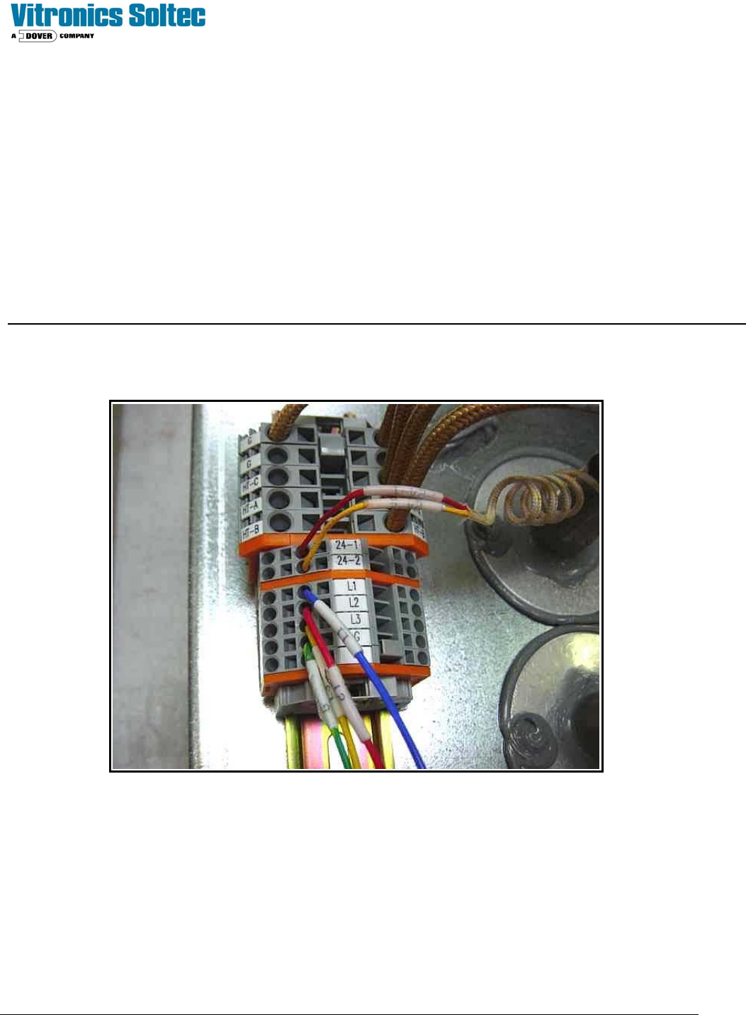
On the back (top / bottom side) of each heater cell is a terminal block assembly.
Check for either continuity or +24 VDC between terminals 24-1 and 24-2. To read continuity machine power must be
completely disconnected.
To read voltage place the positive lead in terminal 24-1 and the negative lead in ground to verify input voltage to the
switch. If input voltage is present, then move the positive lead to terminal 24-2. If there is no voltage present, the switch
is open. If the switch continuity or voltage checks are good, then move on to the next switch. Is it easiest to start at the
last heat zone on the top and then divide the machine in half for each subsequent check. If the last top heat zone switch
checks good, move directly to the bottom heat cells.
Technical Service Manual 111 Revision Date: August 2004
LIGHT TOWER
The Light Tower is:
! Standard, (installed on all ovens) ) An option, (NOT installed on all ovens)
DESCRIPTION:
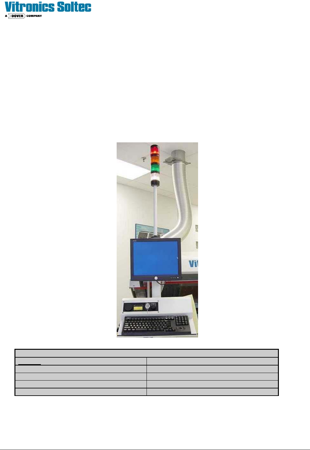
The Light Tower assembly is a mast with four indicating lights mounted on the on-load end of the Reflow Oven. The
lights indicate the status of Oven operation and are duplicates of functions and colors displayed by the Oven Control
Software on the computer screen.
The standard color arrangement is shown below.
(Other configurations are available by special order)
.
LIGHT TOWER LENS COLOR MEANING
COLOR
DESCRIPTION
RED Alarm and Shutdown
WHITE Power “On” / Applied to oven
AMBER Process Warning
GREEN Process Operation Ready (O.K.)
(Refer to Oven schematics for Light Tower and Alarm wiring)

Technical Service Manual 112 Revision Date: August 2004
ON-BOARD OXYGEN (O2) ANALYZER
THE ON-BOARD OXYGEN ANALYZER IS:
!Standard, (installed on all ovens) )An option, (NOT installed on all ovens)
DESCRIPTION:
The On-Board O2 Analyzer is a self-contained unit consisting of an oxygen sensor, pump, and power supply, completely
integrated with the Reflow Oven. The Analyzer is mounted at the rear of the oven behind the lower skins and near the N2
flow meters. The Neutronics model 3100 oxygen analyzer is a 2-piece design. The controller box mounts in a cutout on
the front of the pneumatics panel and the sensor and pump assembly mounts on a bracket on the rear of the pneumatics
panel.
The oxygen sensor consists of a solid state ion conductor of stabilized zirconiumoxide, which is heated to a constant
temperature of 1000 K (727°C). The measured oxygen content is displayed on the face of the Analyzer and on the
computer monitor through the Oven Control Program.
PURPOSE:
XPM
2
Nitrogen ovens are equipped with a single sampling port located in the peak zone (standard) or a 4 port system
(optional) with probes located in the Preheat, Soak, and Reflow zones and Source Gas).
The 4-port option has a rotary 5-way valve located next to the Analyzer. The 5-way valve is used to select the location
from which the Analyzer sample is taken. These sampling ports are used to determine the oxygen content inside the
oven.
APPLICATION:
The Analyzer has controls on its front panel for the operation of the unit. The Analyzer settings should not be changed
during normal oven operation while using nitrogen as an atmosphere. The Analyzer will continuously sample to provide a
real-time measurement of the tunnel atmosphere.
ANALYZER OPERATION
Switching On the Neutronics Model 3100 O2 Analyzer
Configure the O2 analyzer option for the Neutronics Model 3100 on the atmosphere tab.
The 115VAC supply power to the Analyzer is controlled by relay K8 on the A1 board through wire number 52.
The analyzer is switched on whenever the oven is operating in a nitrogen mode.
Entering Neutronics Model 3100 Setup Mode
Press and hold the Mode key for 10 seconds, “CAL” will display on the analyzer while the mode key is held in followed by
“----“ after 10 seconds.
Press the mode key to step through the selections below until the display indicates “4 0”.
Use the up and down arrow keys to change the display to “4 3”.
Press the mode key until the display shows “- “to exit the setup mode and return to the run mode.