Technical_reference - 第115页
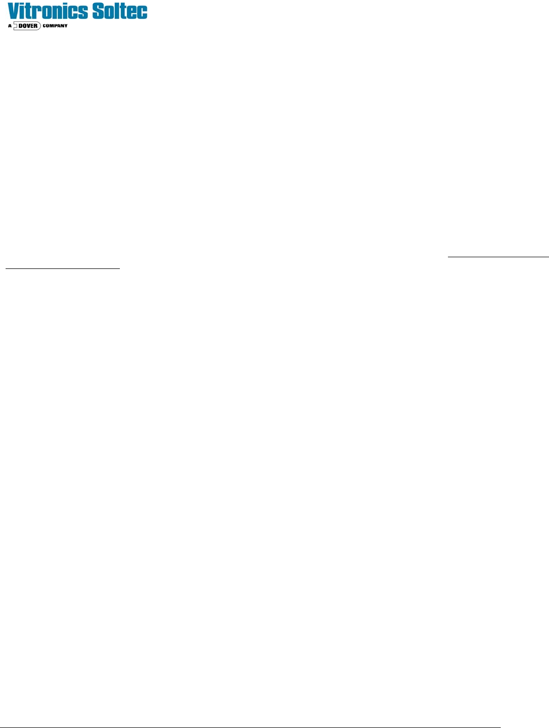
Technical Service Manual 115 Revision Dat e: August 2004 The following diagram shows the Polar Cooling™ option c onfi gured for an oven with three c ooling zones. (Two or four cooling zones would be similar) PolarCool ™ …
Technical Service Manual 114 Revision Date: August 2004
POLAR COOL™ OPTION
Polar Cool™ is:
! Standard (on Nitrogen ovens) ) An option (on all ovens)
DESCRIPTION:
The Polar Cooling™ system is self-contained and mounted to and integrated with the oven. This system does not
require any external service connections to the Reflow Oven.
OPERATION:
The Polar Cool System uses an air-to-liquid-to-air heat collection and discharge system. A cooling fluid (Vitronics SUPER
COOL Part No. 3313350) is pumped through heat exchangers in the cooling cells. Heat is absorbed into the fluid, and
then carried by the cooling fluid to a radiator-fan unit. The heat removed from the cooling cells in the tunnel is then
discharged into room.
Two reusable, easy to remove heat exchangers are mounted in each of the 2, 3 or 4 cooling cells. (The number of
cooling cells depends on the Oven Model)
Technical Service Manual 115 Revision Date: August 2004
The following diagram shows the Polar Cooling™ option configured for an oven with three cooling zones. (Two or four
cooling zones would be similar)
PolarCool ™ and Control Cooling Plumbing Schematic
The cooling fluid is Vitronics SUPER COOL cooling fluid, Part No. 3313350. During normal operation, the cooling
fluid will be warmer than the “dew point temperature” of the room and not warmer than the frame of the oven.
Two thermocouples sense the coolant temperature, which is displayed on the Oven Control Software screen.
DO NOT SUBSTITUTE ANY OTHER FLUID AS COOLANT IN THIS SYSTEM!
Technical Service Manual 116 Revision Date: August 2004
The Polar Cooling™ and Control Cooling system is comprised of three major elements:
1) Heat exchangers,
2) Radiator-Fan Unit,
3) Reservoir-Pump Unit
HEAT EXCHANGERS:
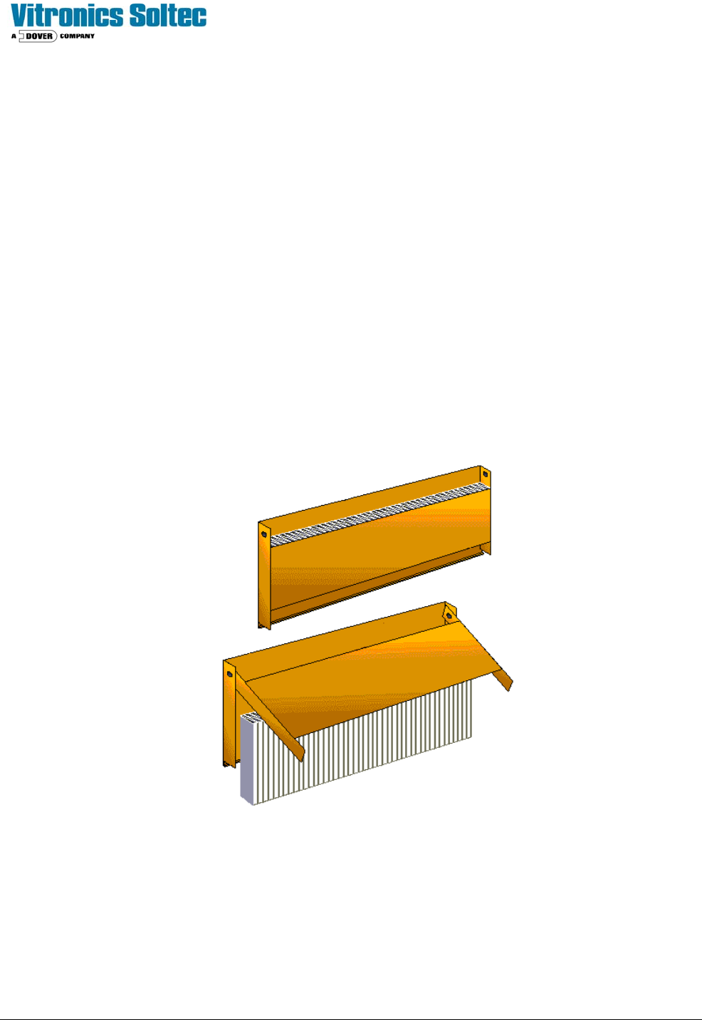
A “cold plate” and a “flux-capture filter” fin assembly combined form a cell heat exchanger.
The cold plate is a gas-to-liquid heat-absorbing aluminum assembly with tubing connections and a serpentine path inside
for coolant flow.
The aluminum fume capture filter/fin element is housed within an aluminum “clam-shell” housing which is seated against
the cold plate. This assembly conducts heat to the cold-plate as well as filters flux vapors from the oven gas.
The filters require periodic maintenance, but can be removed and replaced using a simple hand tool (There is no liquid
connection). Two cam locks in the air recirculation slots of the cooling cells secure the clamshell assembly. Once the
cam locks are released, the "clam shell" housing can be removed from the cell and opened to expose the filter.
Used filters can be cleaned with isopropyl alcohol and reused, or discarded.
“Clam-Shell” Assembly with fume-capture filters