Technical_reference - 第117页
Technical Service Manual 117 Revision Dat e: August 2004 RA DIATOR-FA N UNIT : The radiator -fan units are at the rear of the Oven, m ounted to the top fram e under the s heet m etal panels near the Of f- load (Exit) end…
Technical Service Manual 116 Revision Date: August 2004
The Polar Cooling™ and Control Cooling system is comprised of three major elements:
1) Heat exchangers,
2) Radiator-Fan Unit,
3) Reservoir-Pump Unit
HEAT EXCHANGERS:
A “cold plate” and a “flux-capture filter” fin assembly combined form a cell heat exchanger.
The cold plate is a gas-to-liquid heat-absorbing aluminum assembly with tubing connections and a serpentine path inside
for coolant flow.
The aluminum fume capture filter/fin element is housed within an aluminum “clam-shell” housing which is seated against
the cold plate. This assembly conducts heat to the cold-plate as well as filters flux vapors from the oven gas.
The filters require periodic maintenance, but can be removed and replaced using a simple hand tool (There is no liquid
connection). Two cam locks in the air recirculation slots of the cooling cells secure the clamshell assembly. Once the
cam locks are released, the "clam shell" housing can be removed from the cell and opened to expose the filter.
Used filters can be cleaned with isopropyl alcohol and reused, or discarded.
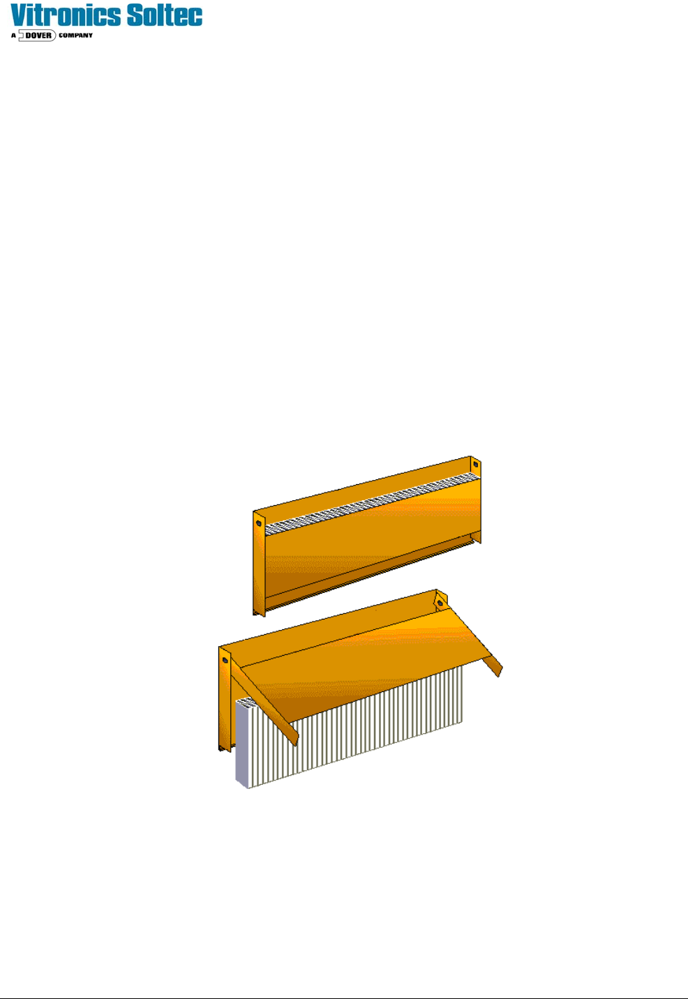
“Clam-Shell” Assembly with fume-capture filters
Technical Service Manual 117 Revision Date: August 2004
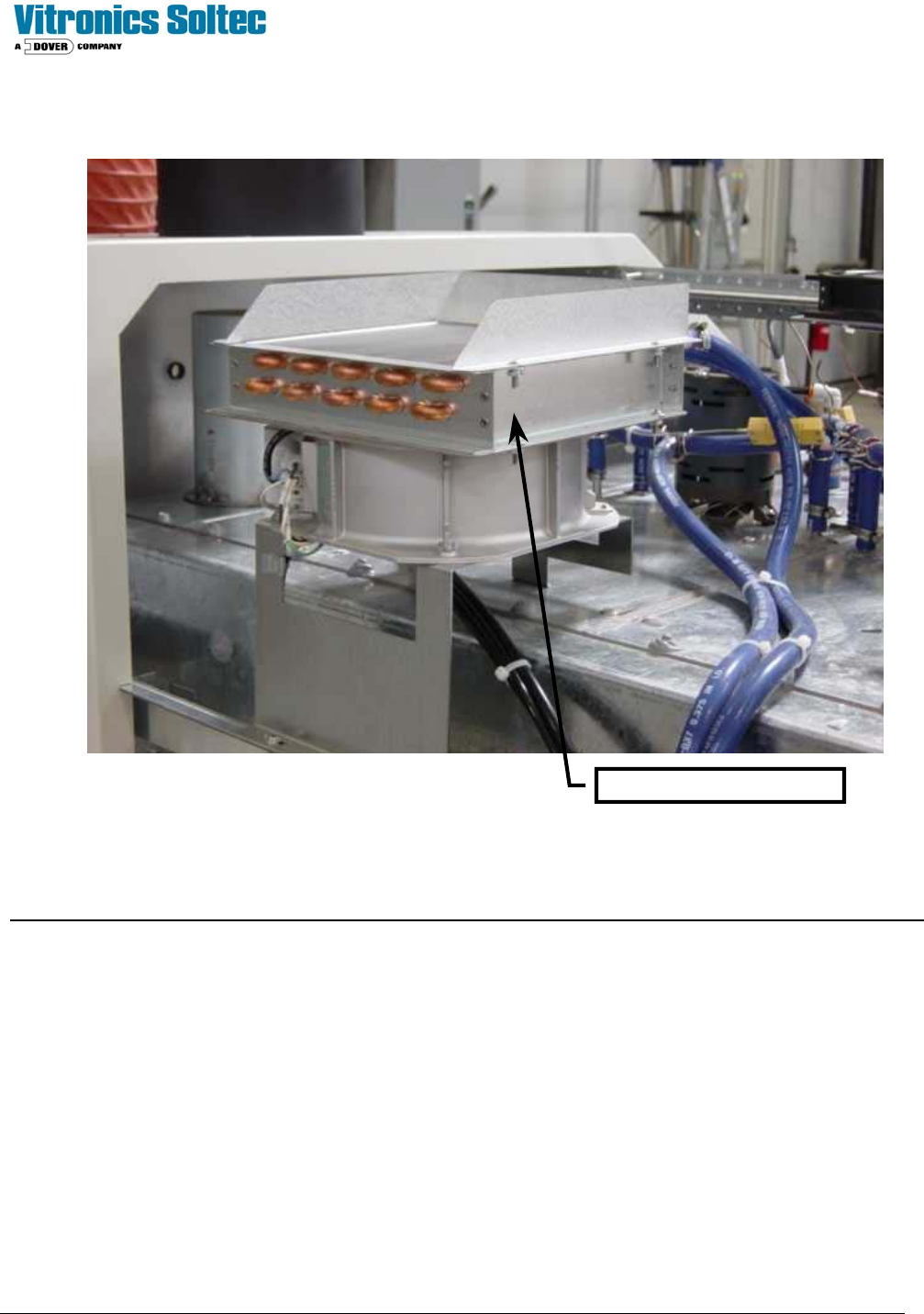
RADIATOR-FAN UNIT:
The radiator-fan units are at the rear of the Oven, mounted to the top frame under the sheet metal panels near the Off-
load (Exit) end of the Oven. Air is forced through the radiator by an axial fan.
Proper operation and cooling cannot take place without adequate airflow through the radiator-fan unit(s).
RADIATOR-FAN UNIT
Technical Service Manual 118 Revision Date: August 2004
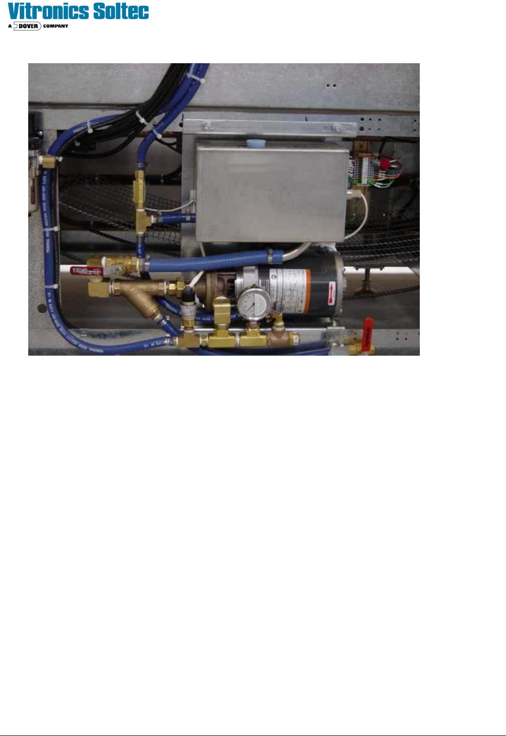
RESERVOIR -PUMP UNIT:
The Reservoir-Pump Unit is mounted on the frame at the rear of oven.
The reservoir is a 1.6 Gallon stainless steel tank. The level switch in the reservoir monitors coolant level and the flow
switch checks return flow. The high-pressure switch trips at 60 PSI. A periodic check of the coolant level in the reservoir
is necessary.
The coolant return line is submerged near the bottom of the reservoir to reduce aeration of the coolant and to help assure
condensation of any returning vapor. The supply line to the coolant pump is in the bottom of the reservoir with a valve for
draining the system. The check valve in the supply line prevents coolant flow back to the reservoir. It also permits
cleaning the in-line strainer without draining the heat exchangers.
The flow switch and level switch are inputs for the Oven Control Program display of the LOW FLOW - LOW COOLANT
alarm.
TESTING:
The motor and supply circuit should be tested. If the Voltage is NOT within the 100 to 120V range recommended, the
transformer connections should be changed according to the changeover chart.
1) Allow the motor to reach a stable temperature with the oven hot.
2) The case temperature of the motor should not exceed 80°C. A normal Pump Motor Case temperature is
about 70 - 80°C at 115V.
3) The internal temperature cut off switch is set for 150° C. (case temperature about 100° C.)
4) If the motor is over temperature, operating at 100 to 116 VAC, it should be replaced.