Technical_reference - 第119页
Technical Service Manual 119 Revision Dat e: August 2004 EXTERNAL COOLIN G LIQUID SU PPLY OPT ION DESCRIPTION: Heat in the cooling cells is absorbed by heat exchangers ( two heat exchangers per top cooling c ell) and con…
Technical Service Manual 118 Revision Date: August 2004
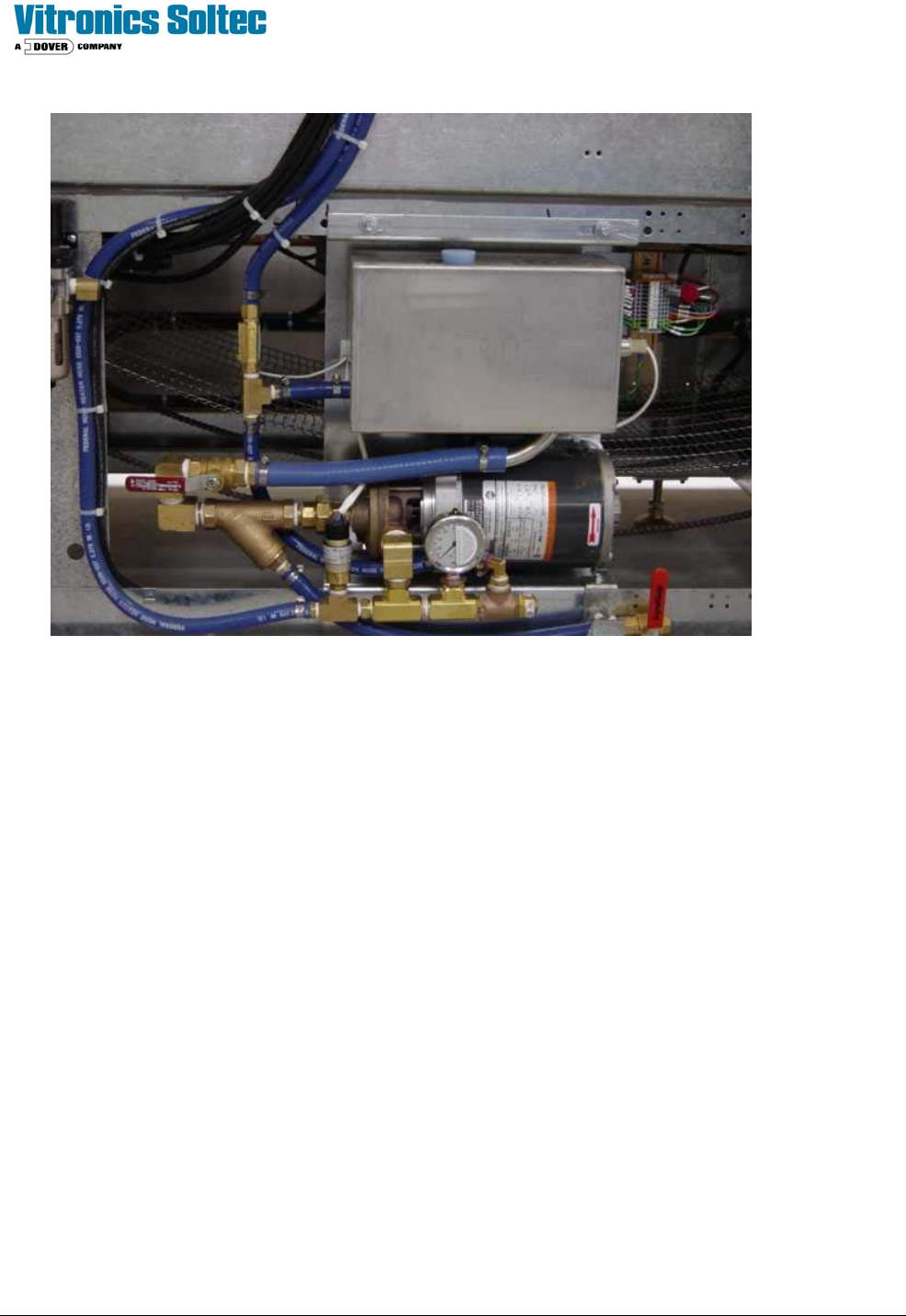
RESERVOIR -PUMP UNIT:
The Reservoir-Pump Unit is mounted on the frame at the rear of oven.
The reservoir is a 1.6 Gallon stainless steel tank. The level switch in the reservoir monitors coolant level and the flow
switch checks return flow. The high-pressure switch trips at 60 PSI. A periodic check of the coolant level in the reservoir
is necessary.
The coolant return line is submerged near the bottom of the reservoir to reduce aeration of the coolant and to help assure
condensation of any returning vapor. The supply line to the coolant pump is in the bottom of the reservoir with a valve for
draining the system. The check valve in the supply line prevents coolant flow back to the reservoir. It also permits
cleaning the in-line strainer without draining the heat exchangers.
The flow switch and level switch are inputs for the Oven Control Program display of the LOW FLOW - LOW COOLANT
alarm.
TESTING:
The motor and supply circuit should be tested. If the Voltage is NOT within the 100 to 120V range recommended, the
transformer connections should be changed according to the changeover chart.
1) Allow the motor to reach a stable temperature with the oven hot.
2) The case temperature of the motor should not exceed 80°C. A normal Pump Motor Case temperature is
about 70 - 80°C at 115V.
3) The internal temperature cut off switch is set for 150° C. (case temperature about 100° C.)
4) If the motor is over temperature, operating at 100 to 116 VAC, it should be replaced.
Technical Service Manual 119 Revision Date: August 2004
EXTERNAL COOLING LIQUID SUPPLY OPTION
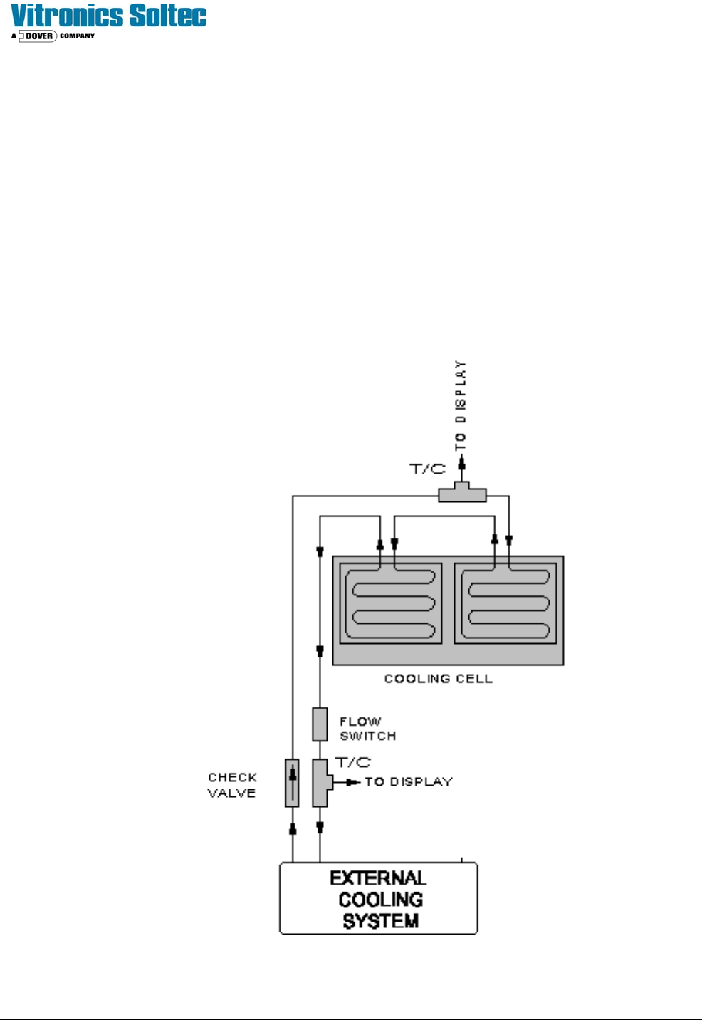
DESCRIPTION:
Heat in the cooling cells is absorbed by heat exchangers (two heat exchangers per top cooling cell) and conducted away
by the cooling fluid supplied by an external cooling system. The external cooling system should meet the following
specifications:
Supply Pressure: 20 to 40 psi [1.38 to 2.76 bar]
Flow Rate: 1 to 3 gpm [4.55 to 13.64 lpm]
Inlet Connection: 1/2" N.P.T
Outlet Connection: 1/2" N.P.T.
NOTE: Vitronics Soltec does not provide hose, clamps and hardware for connections between the reflow system and the
external cooling liquid supply (chiller, plant water, etc.).
Technical Service Manual 120 Revision Date: August 2004
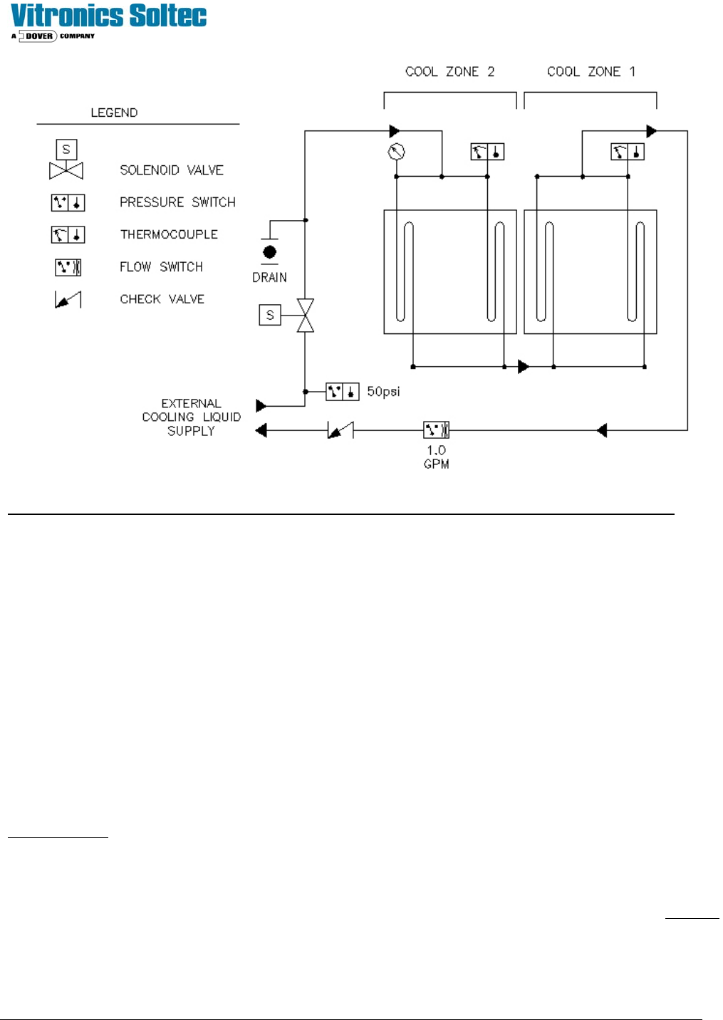
NOTE: This diagram shows the external plumbing connection configured for an oven with two cooling cells.
OPERATION:
The External Cooling Liquid Supply Option is designed to be activated and operated with the reflow system at all times. It
requires a temperature-controlled flow of clean coolant at a constant pressure and flow to the heat exchanger(s). The
coolant temperature should remain above the local dew point when operating to avoid condensation inside the cooling
cells. The system can be drained by using the supplied hose and ball valve attached to the inlet plumbing leg.
SAFETY AND CONTROLS:
Inlet High Pressure Switch: Set to 50 psi, alarms when supply pressure is greater than 50 psi.
Inlet Shut Off Valve: Solenoid valve used to stop flow when machine is inactive
Inlet Pressure Gauge: Gauge used to monitor inlet pressure
Inlet Thermocouple (T/C 1): Monitors inlet cooling liquid temperature
Outlet Thermocouple (T/C 2): Monitors outlet cooling liquid temperature
Flow Switch: Set to 1gpm, alarms when flow falls below set point
Check Valve: Prevents outlet from back filling system
COOLANT SPECIFICATION:
Recommended:
Vitronics Super Cool Part No. 3313350
Distilled Water (recommend use of an additive to prevent algae growth)
Lab grade Propylene Glycol mixed with Distilled Water (20%-80% mixture)
NOTE: De-ionized water or other coolants that will react negatively with the materials used in the system must not to be
used. This will void the machine warranty.