Technical_reference - 第121页
Technical Service Manual 121 Revision Dat e: August 2004 RAIL ADJUST : MANUAL RAIL ADJUST Manual Rail Adjust is : ) Standard, (installed on all ovens with an edge rail conveyor) ! An option, (NOT installed on all ovens) …
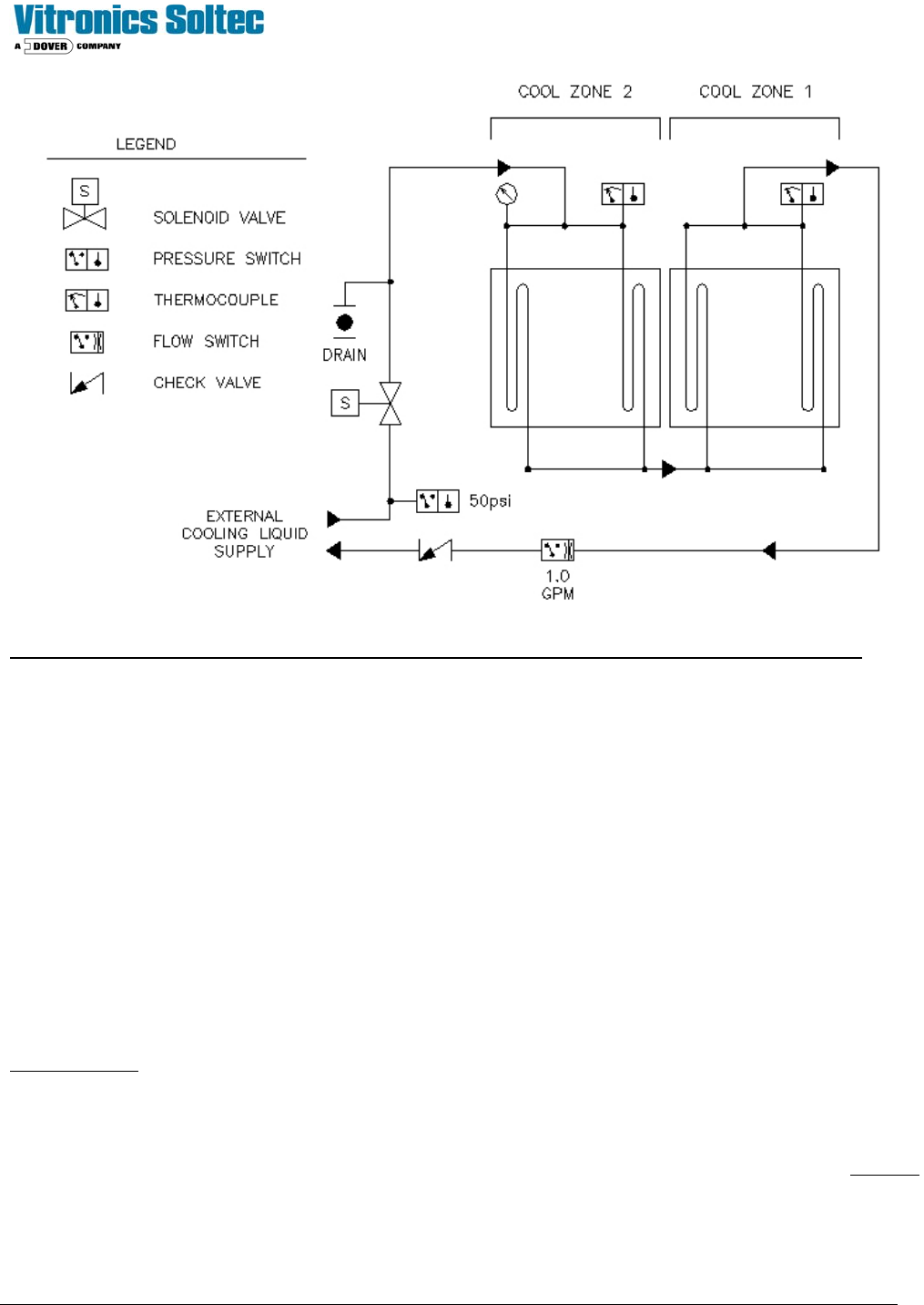
Technical Service Manual 120 Revision Date: August 2004
NOTE: This diagram shows the external plumbing connection configured for an oven with two cooling cells.
OPERATION:
The External Cooling Liquid Supply Option is designed to be activated and operated with the reflow system at all times. It
requires a temperature-controlled flow of clean coolant at a constant pressure and flow to the heat exchanger(s). The
coolant temperature should remain above the local dew point when operating to avoid condensation inside the cooling
cells. The system can be drained by using the supplied hose and ball valve attached to the inlet plumbing leg.
SAFETY AND CONTROLS:
Inlet High Pressure Switch: Set to 50 psi, alarms when supply pressure is greater than 50 psi.
Inlet Shut Off Valve: Solenoid valve used to stop flow when machine is inactive
Inlet Pressure Gauge: Gauge used to monitor inlet pressure
Inlet Thermocouple (T/C 1): Monitors inlet cooling liquid temperature
Outlet Thermocouple (T/C 2): Monitors outlet cooling liquid temperature
Flow Switch: Set to 1gpm, alarms when flow falls below set point
Check Valve: Prevents outlet from back filling system
COOLANT SPECIFICATION:
Recommended:
Vitronics Super Cool Part No. 3313350
Distilled Water (recommend use of an additive to prevent algae growth)
Lab grade Propylene Glycol mixed with Distilled Water (20%-80% mixture)
NOTE: De-ionized water or other coolants that will react negatively with the materials used in the system must not to be
used. This will void the machine warranty.

Technical Service Manual 121 Revision Date: August 2004
RAIL ADJUST:
MANUAL RAIL ADJUST
Manual Rail Adjust is:
) Standard, (installed on all ovens with an edge rail conveyor) !An option, (NOT installed on all ovens)
DESCRIPTION
A PTC (Positive Temperature Coefficient Thermister) limits inrush current and a diode bridge rectifies the 120 VAC
control power for the Rail Adjust Drive Motor. The selector switch mounted at the end of the oven enable this DC voltage
to be applied to the Rail Adjust Drive Motor (providing that the controller has enabled the manual rail adjust function).
Depending upon the polarity of the signal applied to the motor, the motor operates in one direction or the other moving the
rails closer together or further apart. Two limit switches at one end of the oven open the circuit and stop the motor at the
end of travel in or out.
OPERATION
Run the “Manual rail adjust” within the Oven Control Program. NOTE: This operation may require a password.
This activates the rail enable output relay A1-K19. Nothing happens until the rail in/out button is turned. Turn the rail
in/out button in one direction. If the rail motor does not turn, turn the button in the other direction. If the motor still does
not turn, refer to the Oven Schematics and perform the following test procedure:
1 - Disable the manual rail adjust.
2 - Remove the bridge rectifier in the circuit (it should be connected to wires 307,2, 1024, and 1034 at the X10
terminals).
3 - Enable the manual rail adjust: A1-K19 should energize
4 - Select “Rail IN”: A1-K21 & A1-K9 should energize .
5 - Select “Rail OUT”: A1-K22 & A1-K9 & K8 should energize.
6 - If the rail in/out selections do not function, there MAY be a wiring error with the rail selector switch.
7 - After the rail selection logic has been corrected, check to see that the wiring to the motor is correct.
8 - Disable the manual rail adjust.
9 - Replace the bridge rectifier in the circuit connected to wires 307, 2, 1024, and 1034.
(Connect wire 1034 to the (+) terminal, wire 1024 to the (-) terminal, wire 307 to AC! And wire 2 to AC2 at the
X10 terminals).
10 - Using an Ohmmeter in the control enclosure, verify that there is continuity through each rail limit switch. (If
either the switch is wired incorrectly or the rail is pressed up against the limit ,there should not be continuity
through the switch.
11- Enable the manual rail adjust.
12- Check the operation of both the “in” and the “out” adjust switch positions.
13 - Disable the manual rail adjust.

Technical Service Manual 122 Revision Date: August 2004
AUTO RAIL ADJUST
Auto Rail Adjust is:
! Standard, (installed on all ovens) ) An option, (NOT installed on all ovens)
DESCRIPTION
The Oven Control Program automatically adjusts the rail in/out to meet the board size entered in the PRODUCT file in the
Oven Control Program.
OPERATION
Run the Automatic rail adjust within the Oven Operation Program. NOTE: This operation may require a password.
(The direction of travel of the rail and the speed of the width adjust may be selected by choices in the Oven Operation
Program.)
1. Set the rail adjust speed to MAX and select either IN or OUT to move the rail.
2. With the rail width adjustment enabled, select MIN for minimum width speed adjustment. The rail movement should
decrease to a very slow rotation, or stop.
3. Using a Voltmeter on the armature of the Rail Adjust Drive Motor output points, adjust the output voltage to 15 VDC.
The IR COMP potentiometer on the auto rail DC drive should be set to the midpoint position. The TORQUE
potentiometer on the auto rail DC drive should be set to 90%.
4. Run the rail width calibration routine in the Oven Control Program.
While conducting the following tests ensure that the rail does not move to its minimum or maximum value and stop. The
rail adjust system is designed to stop at these positions.
5. Verify that the DC drive card is receiving 120 VAC power between terminals L1 and L2. If not, verify that K37 & K38
are energized.
6. Check that the I/O board relay A1-K9 is energized.
7. Measure and verify that the voltage at wire number 1039 at PX9-20 on the I/O board is +10 VDC.
8. If voltage is present, check the wiring at the signal input of the DC Drive.
9. If the preceding steps check out, measure the DC voltage output of the DC drive circuit board between terminals A1
and A2. Voltage present should be 90-130 VDC. If there is no voltage present, the drive circuit board is likely to be
defective. Otherwise, adjust the SIGNAL ADJUST potentiometer on the DC drive board to produce the 90-130 VDC.
If steps 1-9 have been performed and the rail motor still does not operate, refer to the Oven Schematics and proceed with
the following:
1. Verify that “rail out” control relays K8, A1-K9, A1-K19 & A1-K22 are energized.
2. If A1-K9 is not energized, confirm that A1-K19 & A1-K22 are energized.
3. If A1-K19 & A1-K22 are energized, check the associated wiring.
4. If the rail motor still does not turn, press an e-stop switch to disable 120 VAC control power.
5. Check connections to the K8 relay.
6. Using an Ohm meter, verify that there is continuity through each rail limit switch
(If either the switch is wired incorrectly or the rail is pressed up against the limit switch, there should be no continuity
through the switch.)
7. Pull out the E-stop recently pressed and reset the E-Stop in the Oven Control Program.