Technical_reference - 第126页
Technical Service Manual 126 Revision Dat e: August 2004 SMEMA m achine interf ace for Vitr onics SMEMA04 Januar y 22, 2004 using the A llen Bradley MicroLogix 1200 PLC. There ar e two test procedures below. The fir st t…

Technical Service Manual 125 Revision Date: August 2004
SETUP
The SMEMA interface requires that the connections be made between adjoining machines and the Reflow Oven, using
the SMEMA connectors at the onload and offload ends. The PLC is pre-programmed and the sensors are preset at the
factory. The SMEMA interface is installed and fully tested at the factory before shipping. The user should not need to
adjust the SMEMA interface after initial connections have been made.
OPERATION
Action by the Reflow Oven operator is not necessary for the SMEMA interface to function. As long as the upline /
downline connections are made and a component failure has not occurred, operation will be automatic when the Reflow
Oven is powered up.
NOTE
Ovens with a Dual Rail conveyor (with two sets of rails and chains) have two separate sets SMEMA Interface sensors
making separate input(s) to the PLC.
Each conveyor must be ready to receive product before it independently sends a “Ready” signal to its respective “upline”
equipment.
Either conveyor can send a “Product at Offload” signal to the “downline” equipment.

Technical Service Manual 126 Revision Date: August 2004
SMEMA machine interface
for Vitronics SMEMA04 January 22, 2004
using the Allen Bradley MicroLogix 1200 PLC.
There are two test procedures below. The first test is for PLC units that are installed in an oven, and the second is for
PLC units being tested separately from the oven (stand-alone). The stand-alone test specifies input and output
connections instead of devices (sensors, upstream / downstream machines, etc.). The tests are otherwise identical.
Allen Bradley MicroLogix 1200
PLC Terminal Connections
PLC terminal Wire # Description
24 COM 2007 DC common from PLC, On-load (SX200-4,SX201-4), Off-load
(SX202-2,SX203-2)
24 VDC 2003 24VDC from PLC, COM 0, COM 1
IN 0 - Not used
IN 1 2008 On-load lane #1 product sensor
IN 2 2038 On-load lane #2 product sensor
IN 3 2009 Oven ready
IN 4 2018 Off-load lane #1 product sensor
IN 5 2048 Off-load lane #2 product sensor
IN 6 2014 Downstream machine lane #1 ready (SX202-1) W189A
IN 7 2044 Downstream machine lane #2 ready (SX203-1) W189B
IN 8 - Not used
IN 9 - Not used
IN 10 - Not used
IN 11 - Not used
IN 12 - Not used
IN 13 - Not used
COM 0 2003 Input common for IN 0 through IN 3 (24VDC)
COM 1 2003 Input common for IN 4 through IN 13 (24VDC)
L1 18 115 VAC hot
NEUT 2 115 VAC neutral
G G Protective ground
DC 0 2020 Output common for OUT 0 (SX200-1) W190A
OUT 0 2022 Oven ready to upstream lane #1 (SX200-2) W190A
DC 1 2040 Output common for OUT 1 (SX201-1) W190B
OUT 1 2042 Oven ready to upstream lane #2 (SX201-2) W190B
DC 2 2021 Output common for OUT 2 and OUT 3 (SX202-3) W189A
OUT 2 2023 Product available to downstream lane #1 (SX202-4) W189A
OUT 3 - Not used
DC 3 2051 Output common for OUT 4 and OUT 5 (SX203-3) W189B
OUT 4 2053 Product available to downstream lane #2 (SX203-4) W189B
OUT 5 - Not used (Always on when PLC is in run mode)
DC 4 - Output common for OUT 6 through OUT 9
OUT 6 - Downstream lane #1 alarm (product jam or not ready)
OUT 7 - Downstream lane #2 alarm (product jam or not ready)
OUT 8 - Not used
OUT 9 - Not used
Technical Service Manual 127 Revision Date: August 2004
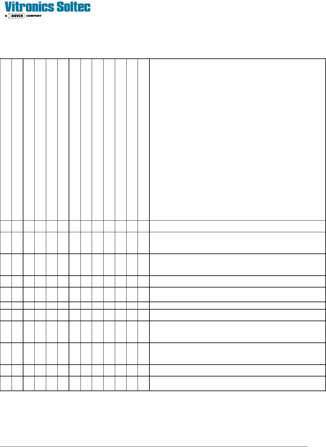
PLC SMEMA program logic table
Logic states 1=ON (corresponding led on PLC is active), 2=OFF, X=Don’t care
IN 1 (2008) On-load lane #1 sensor
IN 2 (2038) On-load lane #2 sensor
IN 3 (2009) oven ready
IN 4 (2018) Off-load lane #1 sensor
IN 5 (2048) Off-load lane #2 sensor
IN 6 (2014) Downstream lane #1 ready
IN 7 (2044) Downstream lane #2 ready
OUT 0 (2022) Oven ready to lane #1 upstream
OUT 1 (2042) Oven ready to lane #2 upstream
OUT 2 (2023) Product available to lane #1 downstream
OUT 4 (2053) Product available to lane #2 downstream
OUT 6 Lane #1 downstream alarm
OUT 7 Lane #2 downstream alarm
Operation
1 X 1 X X 1 X 1 X X X 0 X Lane #1 Start transfer of product from lane #1 upstream
1X1XX1X0XXX0X
Lane #1 Oven ready to upstream shuts off during transfer
and remains off for additional time based on potentiometer
zero setting on PLC for product spacing
XX1XX0X0XXX1X
Lane #1 on-load product transfer is suspended after
downstream lane #1 ready signal is absent beyond 30
seconds
X X X 1 X X X X X 1 X 0 X Lane #1 transfer of product to downstream
XXX1XXX0X1X1X
Lane #1 product jam alarm occurs after product has been
present at the off-load sensor beyond 180 seconds
X 1 1 X X X 1 X 1 X X X 0 Lane #2 Start transfer of product from lane #2 upstream
X11XXX1X0XXX0
Lane #2 Oven ready to upstream shuts off during transfer
and remains off for additional time based on potentiometer
one setting on PLC for product spacing
XX1XXX0X0XXX1
Lane #2 on-load product transfer is suspended after
downstream lane #2 ready signal is absent beyond 30
seconds
X X X X 1 X X X X X 1 X 0 Lane #2 transfer of product to downstream
XXXX1XXX0X1X1
Lane #2 product jam alarm occurs after product has been
present at the off-load sensor beyond 180 seconds