Technical_reference - 第127页
Technical Service Manual 127 Revision Dat e: August 2004 PLC SMEMA program logic table Logic states 1=ON (cor responding led on PL C is ac tive), 2=OF F, X=Don’t car e IN 1 (2008) On- load lane #1 sensor IN 2 (2038) On- …

Technical Service Manual 126 Revision Date: August 2004
SMEMA machine interface
for Vitronics SMEMA04 January 22, 2004
using the Allen Bradley MicroLogix 1200 PLC.
There are two test procedures below. The first test is for PLC units that are installed in an oven, and the second is for
PLC units being tested separately from the oven (stand-alone). The stand-alone test specifies input and output
connections instead of devices (sensors, upstream / downstream machines, etc.). The tests are otherwise identical.
Allen Bradley MicroLogix 1200
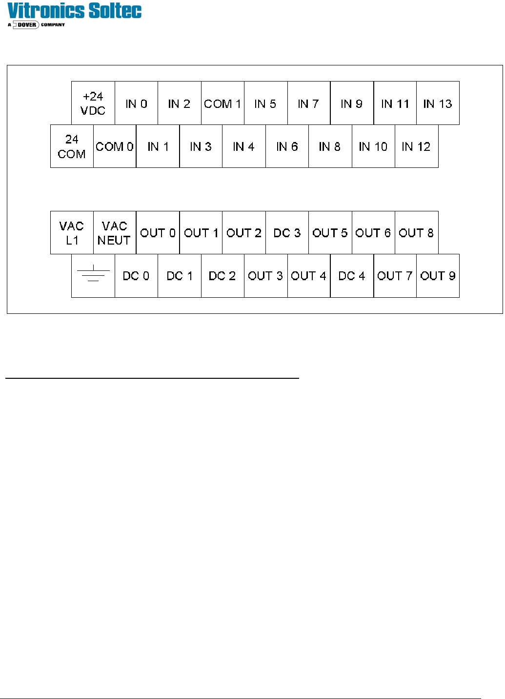
PLC Terminal Connections
PLC terminal Wire # Description
24 COM 2007 DC common from PLC, On-load (SX200-4,SX201-4), Off-load
(SX202-2,SX203-2)
24 VDC 2003 24VDC from PLC, COM 0, COM 1
IN 0 - Not used
IN 1 2008 On-load lane #1 product sensor
IN 2 2038 On-load lane #2 product sensor
IN 3 2009 Oven ready
IN 4 2018 Off-load lane #1 product sensor
IN 5 2048 Off-load lane #2 product sensor
IN 6 2014 Downstream machine lane #1 ready (SX202-1) W189A
IN 7 2044 Downstream machine lane #2 ready (SX203-1) W189B
IN 8 - Not used
IN 9 - Not used
IN 10 - Not used
IN 11 - Not used
IN 12 - Not used
IN 13 - Not used
COM 0 2003 Input common for IN 0 through IN 3 (24VDC)
COM 1 2003 Input common for IN 4 through IN 13 (24VDC)
L1 18 115 VAC hot
NEUT 2 115 VAC neutral
G G Protective ground
DC 0 2020 Output common for OUT 0 (SX200-1) W190A
OUT 0 2022 Oven ready to upstream lane #1 (SX200-2) W190A
DC 1 2040 Output common for OUT 1 (SX201-1) W190B
OUT 1 2042 Oven ready to upstream lane #2 (SX201-2) W190B
DC 2 2021 Output common for OUT 2 and OUT 3 (SX202-3) W189A
OUT 2 2023 Product available to downstream lane #1 (SX202-4) W189A
OUT 3 - Not used
DC 3 2051 Output common for OUT 4 and OUT 5 (SX203-3) W189B
OUT 4 2053 Product available to downstream lane #2 (SX203-4) W189B
OUT 5 - Not used (Always on when PLC is in run mode)
DC 4 - Output common for OUT 6 through OUT 9
OUT 6 - Downstream lane #1 alarm (product jam or not ready)
OUT 7 - Downstream lane #2 alarm (product jam or not ready)
OUT 8 - Not used
OUT 9 - Not used

Technical Service Manual 127 Revision Date: August 2004
PLC SMEMA program logic table
Logic states 1=ON (corresponding led on PLC is active), 2=OFF, X=Don’t care
IN 1 (2008) On-load lane #1 sensor
IN 2 (2038) On-load lane #2 sensor
IN 3 (2009) oven ready
IN 4 (2018) Off-load lane #1 sensor
IN 5 (2048) Off-load lane #2 sensor
IN 6 (2014) Downstream lane #1 ready
IN 7 (2044) Downstream lane #2 ready
OUT 0 (2022) Oven ready to lane #1 upstream
OUT 1 (2042) Oven ready to lane #2 upstream
OUT 2 (2023) Product available to lane #1 downstream
OUT 4 (2053) Product available to lane #2 downstream
OUT 6 Lane #1 downstream alarm
OUT 7 Lane #2 downstream alarm
Operation
1 X 1 X X 1 X 1 X X X 0 X Lane #1 Start transfer of product from lane #1 upstream
1X1XX1X0XXX0X
Lane #1 Oven ready to upstream shuts off during transfer
and remains off for additional time based on potentiometer
zero setting on PLC for product spacing
XX1XX0X0XXX1X
Lane #1 on-load product transfer is suspended after
downstream lane #1 ready signal is absent beyond 30
seconds
X X X 1 X X X X X 1 X 0 X Lane #1 transfer of product to downstream
XXX1XXX0X1X1X
Lane #1 product jam alarm occurs after product has been
present at the off-load sensor beyond 180 seconds
X 1 1 X X X 1 X 1 X X X 0 Lane #2 Start transfer of product from lane #2 upstream
X11XXX1X0XXX0
Lane #2 Oven ready to upstream shuts off during transfer
and remains off for additional time based on potentiometer
one setting on PLC for product spacing
XX1XXX0X0XXX1
Lane #2 on-load product transfer is suspended after
downstream lane #2 ready signal is absent beyond 30
seconds
X X X X 1 X X X X X 1 X 0 Lane #2 transfer of product to downstream
XXXX1XXX0X1X1
Lane #2 product jam alarm occurs after product has been
present at the off-load sensor beyond 180 seconds
Technical Service Manual 128 Revision Date: August 2004
Allen Bradley MicroLogix 1200 Terminal Detail
Procedure for testing the SMEMA Machine Interface on an oven
The SMEMA operation of each lane is independent in the PLC. Each lane can be tested separately or together without
effecting the other.
1) Allow the oven to get into a process ready state by operating a belt recipe or by installing a jumper wire between the
IN 3 and the 24 COM terminal on the PLC. IN 3 on the PLC should be on.
Lane 1 Testing
2) Install a mating connector on the off-load connector of the oven with a jumper installed between pins 1 and 2, cable
W189A to provide the downstream machine ready signal to the PLC. Or install a jumper wire on the electrical panel
on terminal block X30 between wire numbers 2014 and 2007. IN 6 on the PLC should be on.
3) Connect the flashlight end of the test equipment to the on-load connector of the oven, cable W190A or install 2 wires
in a mating plug connector on pins 1 and 2 and connect the free ends to an external ohm meter or continuity tester.
4) OUT 0 on the PLC should be on and the test equipment on the on-load end of the oven should be on to indicate that
the oven is ready to accept product from the upstream machine lane 1.
5) Turn the top potentiometer (zero) on the PLC fully counter clockwise for minimum product spacing. The
potentiometers on the Allen Bradley PLC are located behind a removable access plate on the front lower left of the
PLC below the Allen Bradley logo.
The test equipment on the on-load of the oven should follow OUT 0 on the PLC in the following tests.
6) Run a test product under the on-load sensor for lane 1 and verify that OUT 0 goes off on the PLC while the product is
under the on-load sensor and remains off for an additional second after the on-load sensor is clear.