Technical_reference - 第129页
Technical Service Manual 129 Revision Dat e: August 2004 7) T urn the top potentiom eter (zero) on the PLC ½ turn cloc kwise. Run a tes t product under the on- load sensor f or lane #1 and verify that OUT 0 rem ains off …
Technical Service Manual 128 Revision Date: August 2004
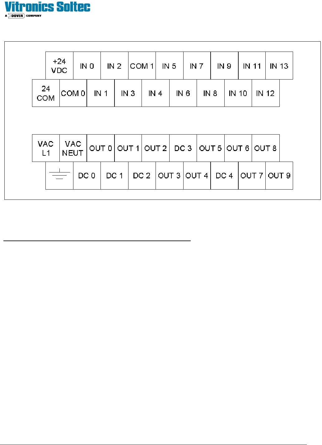
Allen Bradley MicroLogix 1200 Terminal Detail
Procedure for testing the SMEMA Machine Interface on an oven
The SMEMA operation of each lane is independent in the PLC. Each lane can be tested separately or together without
effecting the other.
1) Allow the oven to get into a process ready state by operating a belt recipe or by installing a jumper wire between the
IN 3 and the 24 COM terminal on the PLC. IN 3 on the PLC should be on.
Lane 1 Testing
2) Install a mating connector on the off-load connector of the oven with a jumper installed between pins 1 and 2, cable
W189A to provide the downstream machine ready signal to the PLC. Or install a jumper wire on the electrical panel
on terminal block X30 between wire numbers 2014 and 2007. IN 6 on the PLC should be on.
3) Connect the flashlight end of the test equipment to the on-load connector of the oven, cable W190A or install 2 wires
in a mating plug connector on pins 1 and 2 and connect the free ends to an external ohm meter or continuity tester.
4) OUT 0 on the PLC should be on and the test equipment on the on-load end of the oven should be on to indicate that
the oven is ready to accept product from the upstream machine lane 1.
5) Turn the top potentiometer (zero) on the PLC fully counter clockwise for minimum product spacing. The
potentiometers on the Allen Bradley PLC are located behind a removable access plate on the front lower left of the
PLC below the Allen Bradley logo.
The test equipment on the on-load of the oven should follow OUT 0 on the PLC in the following tests.
6) Run a test product under the on-load sensor for lane 1 and verify that OUT 0 goes off on the PLC while the product is
under the on-load sensor and remains off for an additional second after the on-load sensor is clear.

Technical Service Manual 129 Revision Date: August 2004
7) Turn the top potentiometer (zero) on the PLC ½ turn clockwise. Run a test product under the on-load sensor for lane
#1 and verify that OUT 0 remains off approximately 30 seconds after the on-load sensor is clear.
8) Return the top potentiometer (zero) on the PLC to the fully counter-clockwise setting.
9) Remove the mating connector on the off-load connector of the oven or the jumper wire that was installed previously in
step 2. Verify that after 30 seconds OUT 0 is off on the PLC to indicate that the oven is no longer ready to accept
product on lane #1.
10) Run a product or object under the off-load sensor for lane #1 and verify that OUT 2 on the PLC comes on and
remains on until the off-load sensor is clear to indicate that product is available to a downstream machine.
Lane 2 Testing
1. Install a mating connector on the off-load connector of the oven with a jumper installed between pins 1 and 2, cable
W189B to provide the downstream machine ready signal to the PLC. Or install a jumper wire on the electrical panel
on terminal block X30 between wire numbers 2044 and 2007. IN 7 on the PLC should be on.
2. Connect the flashlight end of the test equipment to the on-load connector of the oven, cable W190B or install 2 wires
in a mating plug connector on pins 1 and 2 and connect the free ends to an external ohm meter or continuity tester.
3. OUT 1 on the PLC should be on and the test equipment on the on-load end of the oven should be on to indicate that
the oven is ready to accept product from the upstream machine lane 2.
4. Turn the bottom potentiometer (one) on the PLC fully counter clockwise for minimum product spacing. The
potentiometers on the Allen Bradley PLC are located behind a removable access plate on the front lower left of the
PLC below the Allen Bradley logo.
5. The test equipment on the on-load of the oven should follow OUT 1 on the PLC in the following tests.
6. Run a test product under the on-load sensor for lane 2 and verify that OUT 1 goes off on the PLC while the product is
under the on-load sensor and remains off for an additional second after the on-load sensor is clear.
7. Turn the bottom potentiometer (one) on the PLC ½ turn clockwise. Run a test product under the on-load sensor for
lane #2 and verify that OUT 1 remains off approximately 30 seconds after the on-load sensor is clear.
8. Return the bottom potentiometer (one) on the PLC to the fully counter-clockwise setting.
9. Remove the mating connector on the off-load connector of the oven or the jumper wire that was installed previously in
step 2. Verify that after 30 seconds OUT 1 is off on the PLC to indicate that the oven is no longer ready to accept
product on lane #2.
10. Run a product or object under the off-load sensor for lane #2 and verify that OUT 4 on the PLC comes on and
remains on until the off-load sensor is clear to indicate that product is available to a downstream machine.
End of on oven test.
Notes:
When the flashlight for the on-load end is on, the oven is ready to accept product. The flashlight will come on if:
1. The oven is process ready,
2. There is no product under the on-load sensor,
3. The downstream machine is ready, and
4. No downstream alarm conditions have been detected by the PLC.
A downstream alarm condition is indicated by OUT 6 for lane 1 and OUT 7 for lane 2.
The SMEMA interface for each of the two lanes operates independently through shared inputs on the PLC. The
second lane can be left unconnected on an oven with only one lane of SMEMA interface.
If the PLC does not comply with any of the test conditions, then it needs to be
reprogrammed or replaced.

Technical Service Manual 130 Revision Date: August 2004
Procedure for Stand-alone SMEMA Machine Interface Test
Required Equipment:
Pre-programmed PLC - Vitronics Soltec part number 1476902
3 wire "cheater cord" - power cord with stripped back wires on one end and a plug for a 115 Volt outlet on the other
10 jumper wires (24 to 16 AWG) each approximately 4 inches long.
Small screwdriver (flat or phillips) for adjusting the trim potentiometers.
The SMEMA operation of each lane is independent in the PLC. Each lane can be tested separately or together without
effecting the other.
1) Connect the following jumper wires: From 24VDC to COM 0 and to COM 1 terminals on the PLC. From 24 COM to I
3 to I 6 and then to I 7 on the PLC. Connect one additional test wire on the PLC from the 24 COM terminal and leave
the other end unconnected (not touching anything).
2) Connect the 3 wire cheater cord to the power terminals: green or green/yellow to the protective earth ground, white
or light blue to neutral ( NEUT ), and the remaining wire (typically red, black, or brown) to the "hot" or "line" terminal (
L1 ).
3) Plug the cheater cord into a standard 115 Volt outlet. The lights on the PLC should flash for a few seconds, while the
PLC is running self-diagnostics. The "power" and "run" lights on the front of the PLC should remain on.
Lane 1 Testing
4) OUT 0 on the PLC should be on to indicate that the oven is ready to accept product from the upstream machine lane
1.
5) Turn the top potentiometer (zero) on the PLC fully counter clockwise for minimum product spacing. The
potentiometers on the Allen Bradley PLC are located behind a removable access plate on the front lower left of the
PLC below the Allen Bradley logo.
6) Touch and hold the free end of the test wire to the IN 1 terminal on the PLC. Verify that OUT 0 goes off on the PLC
while the test wire is connected to IN 1 and remains off for an additional second after the test wire is moved off of the
IN 1 terminal.
7) Turn the top potentiometer (zero) on the PLC ½ turn clockwise. Touch and hold the free end of the test wire to the IN
1 terminal on the PLC. Verify that OUT 0 remains off approximately 30 seconds after the test wire is moved off of the
IN 1 terminal.
8) Return the top potentiometer (zero) on the PLC to the fully counter-clockwise setting.
9) Temporarily disconnect the wire(s) connected to terminal I 6 on the PLC. Verify that after 30 seconds OUT 0 is off on
the PLC to indicate that the oven is no longer ready to accept product on lane #1.
10) Touch and hold the free end of the test wire to terminal I 4 on the PLC and verify that OUT 2 on the PLC comes on
and remains on until the test wire is removed to indicate that product is available to a downstream machine.
Lane 2 Testing
1. OUT 1 on the PLC should be on to indicate that the oven is ready to accept product from the upstream machine lane
2.
2. Turn the bottom potentiometer (one) on the PLC fully counter clockwise for minimum product spacing. The
potentiometers on the Allen Bradley PLC are located behind a removable access plate on the front lower left of the
PLC below the Allen Bradley logo.
3. Touch and hold the free end of the test wire to the IN 2 terminal on the PLC. Verify that OUT 1 goes off on the PLC
while the test wire is connected to IN 2 and remains off for an additional second after the test wire is moved off of the
IN 2 terminal.