Technical_reference - 第14页
Technical Service Manual 14 Revision Dat e: August 2004 HEAT CONT ROL O VERVIEW The elec trical portion of the Heat Control System cons ists of three m ajor par ts: 1) POWER SOURCE: Three Phas e power is provided to the …
Technical Service Manual 13 Revision Date: August 2004
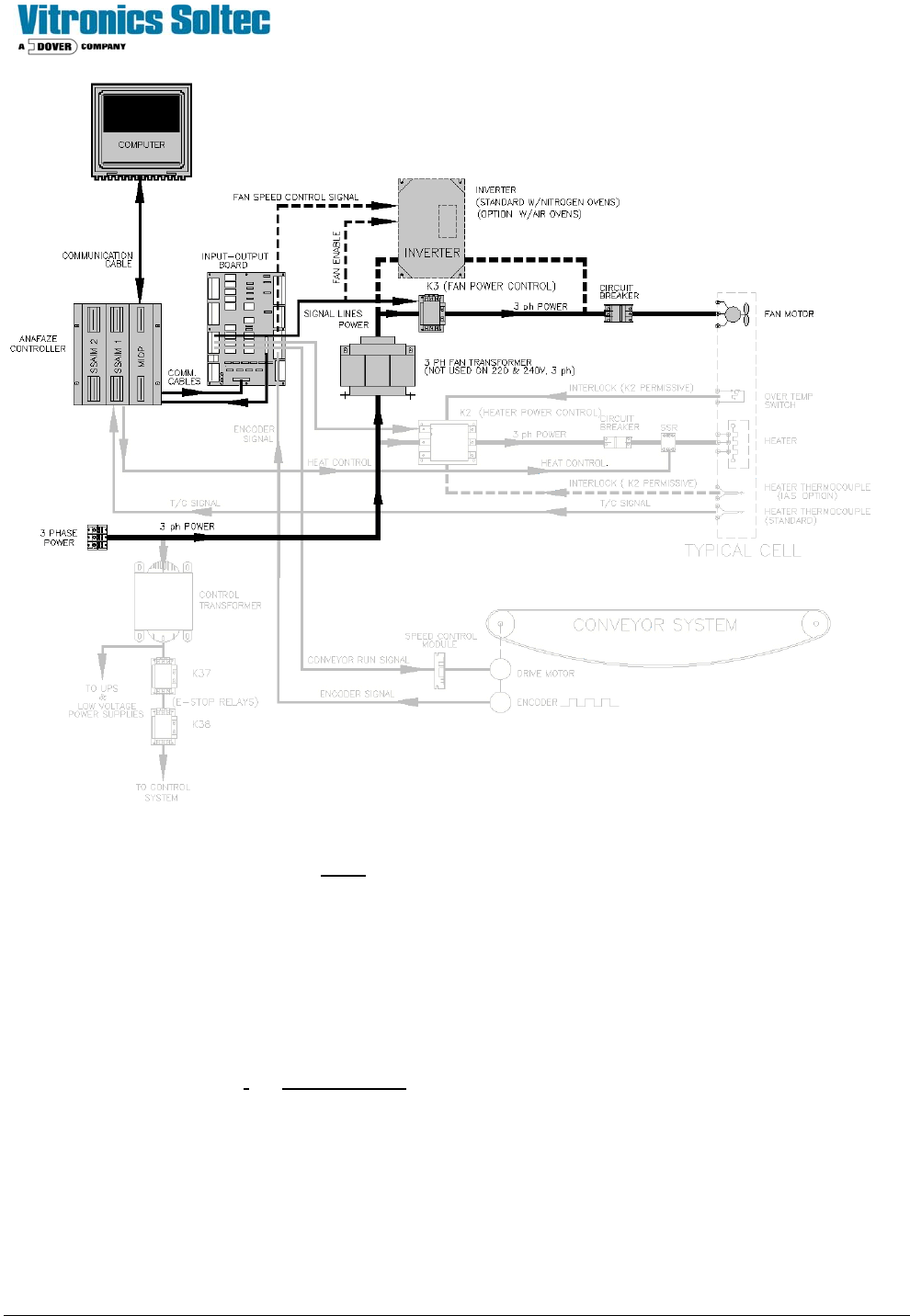
FAN CONTROL OVERVIEW
1) POWER SOURCE:
3 Phase power is provided to either the line terminals of the Fan Contactor (K13), the primary side of the
INVERTER, or 3 phase Fan Transformer, or the 3-phase line filter depending on the Oven options and Operating
Voltage.
2) CONTROL ELEMENTS:
Air-Only Ovens:
FAN CONTACTOR (K13) coil is energized by I/0 Board Output Relay A1-K2, K13’s contacts close, 3 phase
power is permitted to flow to/through the Fan CIRCUIT BREAKER(s). (F41 for all upper Fans & F42 for all lower
Fans) to the Fans for Full-Speed On/Off Control.
Nitrogen Option Ovens:
FAN CONTACTOR (K13)
does not exist. I/0 Board Output Relay A1-K2, in this case, serves as the Enable
input to the INVERTER. An analog (modulated) Low Voltage D.C. output from the CONTROLLER signals the
INVERTER to vary it’s output frequency to the Fans, resulting in variable-speed Control of the Fans.
3) FANS:
The FAN MOTORS are Open Frame, 3 Phase, 50/60 Hz, 1/6 Hp, 2800-3400 RPM @ rated frequency,
continuous duty.
Technical Service Manual 14 Revision Date: August 2004
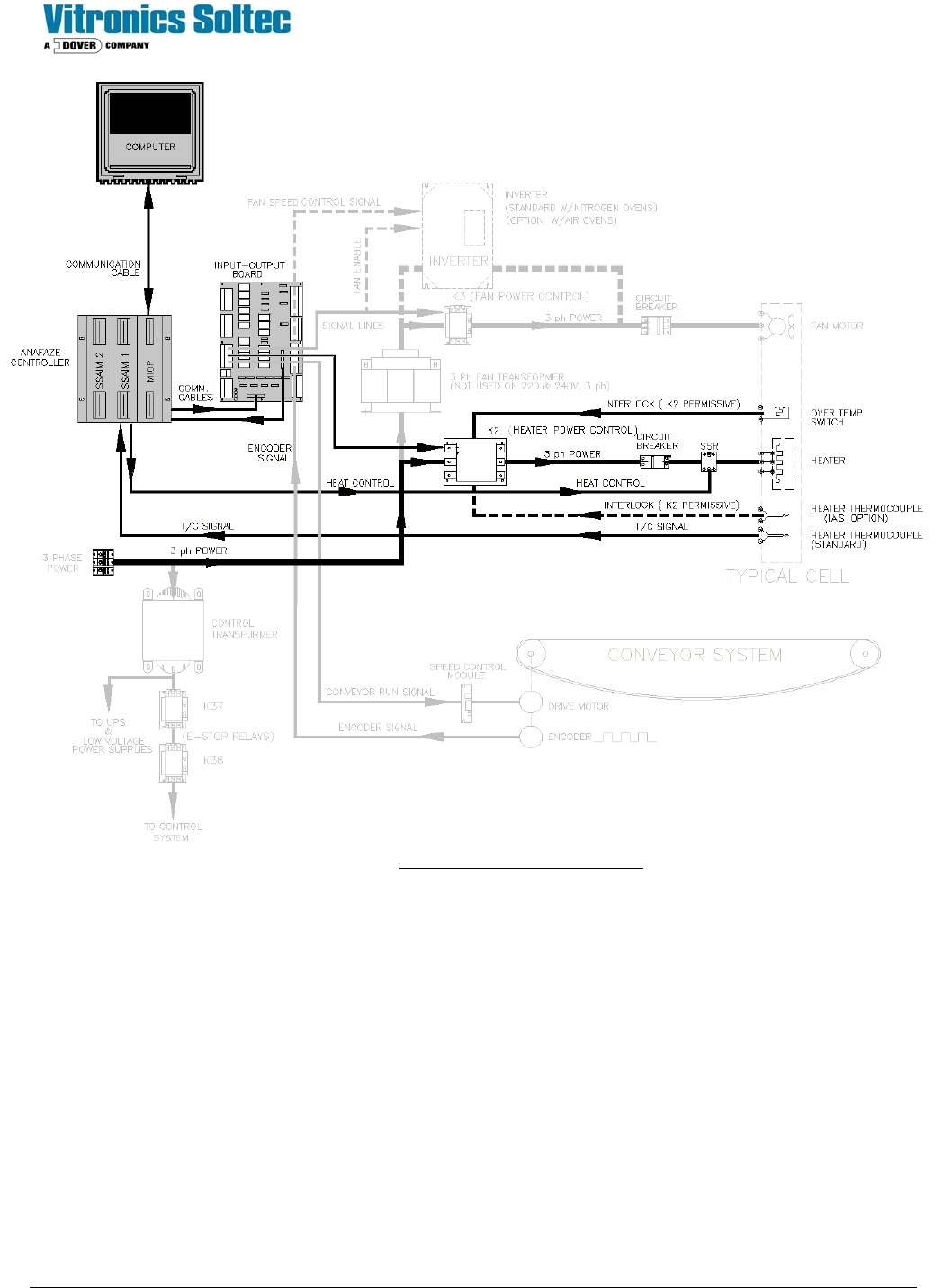
HEAT CONTROL OVERVIEW
The electrical portion of the Heat Control System consists of three major parts:
1) POWER SOURCE:
Three Phase power is provided to the line terminals of the Heater Contactor (K2).
2) CONTROL ELEMENTS:
A) POWER DEVICES:
HEATER CONTACTOR (K2) coil is energized by I/0 Board Output Relay A1-K5, (see Interlocks, below) it’s
contacts close, three phase power is permitted to flow to the Heater CIRCUIT BREAKER(s). (Each Heater has
it’s own Circuit Breaker) and to the SSRs (one Solid State Relay for each Heater) which is the final Heater power
control element.
Technical Service Manual 15 Revision Date: August 2004
2- B) INTERLOCKS:
1. Over Temp Switch (es):
Bi-metallic snap switch (es) mounted on each Cell Assembly, open when the temperature exceeds normal operating
temperature of the Cell. They are all wired in series and power the coil of K4. (K4 is not shown on this Overview)
The coil of K2 is wired through the contacts of K4. When an over temperature switch opens, voltage to the coil of K4
is lost. This will cause K2 to de-energize, and ALL power will be removed from ALL
heaters.
(K4 also signals the Controller to shut the Oven down)
2. Heater Thermocouple (IAS Option)
A Heater mounted thermocouple connected to the Independent Alarm Scanner option. The IAS output contacts are
wired in series with the cell over temperature switches and power to the coil of K4. (K4 is not shown on this Overview)
The coil of K2 is wired through the contacts of K4. When an over temperature condition is sensed, the I.A.S board
contacts open and voltage to the coil of K4 is lost. This will cause K2 to de-energize, and ALL power will be removed
from ALL heaters. (K4 also signals the Controller to shut the Oven down)
3) Heater Thermocouple (Standard)
A Heater mounted thermocouple(s) to sense the temperature of the Heat Cell and connected to the Controller for
heater control.
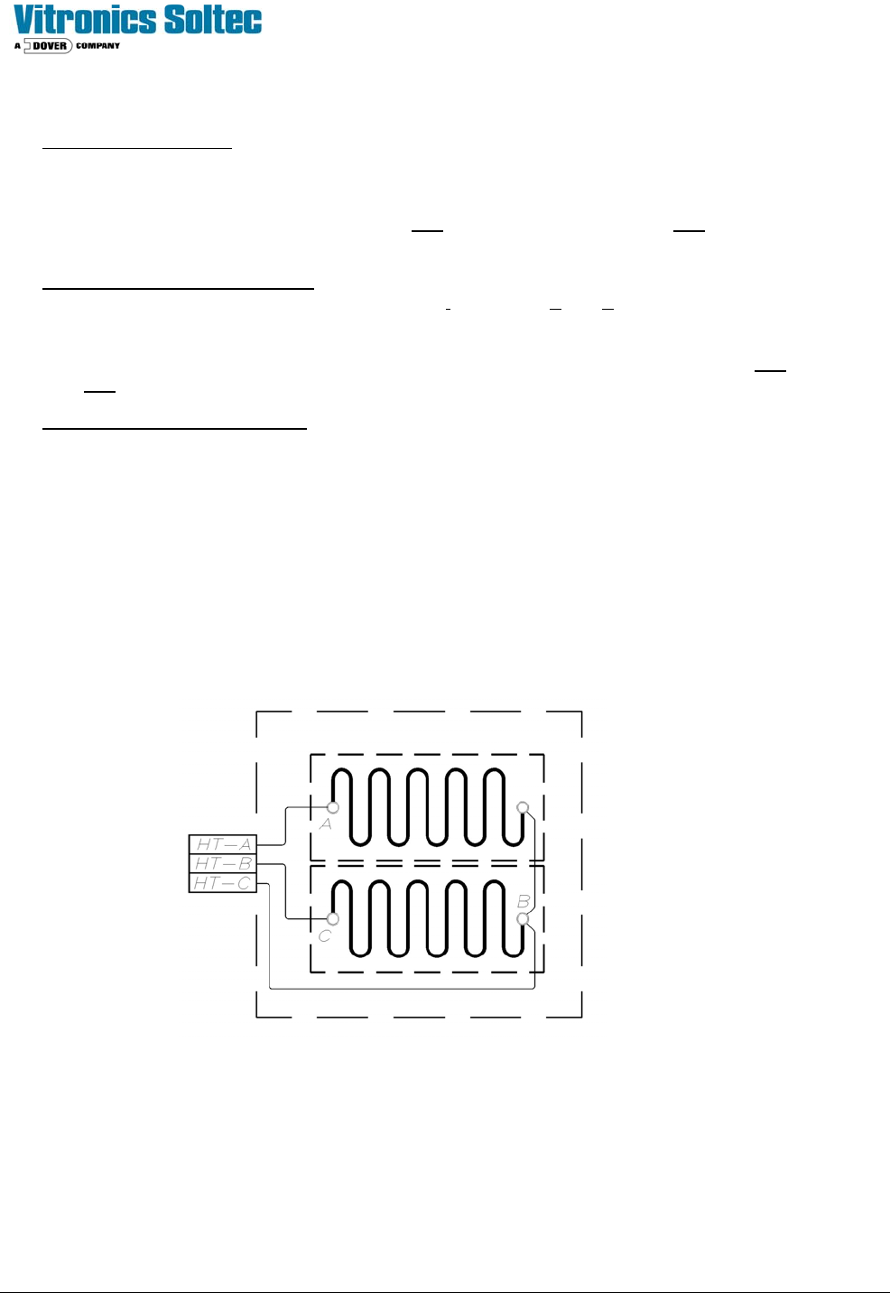
3) HEATERS:
Each Heater Assembly has two large flat Inconel elements (resistors) mounted between two aluminum plates.
Each pair of elements may be wired in series or parallel, depending on the operating voltage of the oven.
Heater Schematic
See: “Heater Resistance & Replacement
Reference Chart” for resistance values