Technical_reference - 第27页
Technical Service Manual 27 Revision Dat e: August 2004 FA ILED CONT ROL SSR S YMP TOM # 1 A Cell indicates an under tem peratur e condition where the tem perature ris es but does not reac h set point. The Cell m ay not …
Technical Service Manual 26 Revision Date: August 2004
CONTROLLER FAILURE
SYMPTOM # 1
A Cell indicates an over temperature condition with the temperature rapidly rising past set point. The failure of a single
output on the controller is a possibility.
POSSIBLE CAUSES
If a single output on the controller fails with a short to ground, the heater will receive full power continuously. During
normal operation, the SSR receives a ground signal from the controller output, and it turns on the AC power to the heater.
Therefore, when the output shorts to ground, the heater is “ON” all of the time. If this condition occurs, the controller may
or may not be aware of the fault condition, but, could not do anything about it because the failed output was the only way
for the controller to control the heater. These symptoms indicate the need to replace a faulty controller.
HINT: To help isolate this problem, disable the suspect heater in the software and then watch the SSR board LED for
that heater. If the LED is on after the heater has been disabled, then the controller output may be faulty.
SYMPTOM # 2
A Cell indicates an under temperature problem in which the cell appears to stay cold.
This condition can be caused by a controller failure.
POSSIBLE CAUSES
This condition will only occur when starting the oven from a cold state. When/if a single output of the controller fails, it is
most likely to fail “open”. If this happens, the SSR (and its heater) will never be turned “ON”. The SSR requires a ground
signal to turn “ON” to supply AC power to the heater. Should there be a general controller failure, all outputs (and SSRs)
should be “OFF” and all the heaters should be cold. These symptoms indicate the need to replace a faulty controller.
HINT: To help isolate this problem, enable the suspect heater in the software and then watch the SSR board LED for that
heater. If the LED is never on after the heater has been enabled, then the controller may be faulty.
SYMPTOM # 3
A Cell indicates an under temperature condition where the temperature falls from set point.
POSSIBLE CAUSES
This condition can be a result of 1) a controller failure, 2) or loose SSR screws, 3) loose power wires to heater.
HINT: To help isolate this problem, enable the suspect heater in the software and then watch the SSR board LED for that
heater. If the LED is never on after the heater has been enabled, then the controller output is faulty.
NOTE: If the oven is operating and up to temperature, it may take some time for the cell to cool down enough to verify
the state of the output, SSR, and heater.
11
Technical Service Manual 27 Revision Date: August 2004
FAILED CONTROL SSR
SYMPTOM # 1
A Cell indicates an under temperature condition where the temperature rises but does not reach set point.
The Cell may not be heating because the control SSR has failed or is failing.
POSSIBLE CAUSES
When an SSR fails open, power is not supplied to the heater. The Cell temperature rise is probably thermal drift from
nearby cells caused by the Cell Fan motor recirculating air in the tunnel between the Top and Bottom Cells in the zone.
Check the Operating Screen for a heater receiving power at a high percentage rate. The opposite heater in the same
Zone probably is receiving extra power to compensate for the nonfunctioning heater.
If the control SSR fails to operate for ANY reason, the default is to not conduct.
If the SSR fails internally, it could fail in the open state it will not conduct AC power to the heater. Replace the faulty SSR.
When replacing an SSR, use adequate amounts of heat sink compound on the back of the new SSR when mounting it to
the electrical panel.
SYMPTOM # 2
A Cell indicates random high temperatures. The Cell can no longer hold set point because the control SSR has failed or is
failing. This condition may occur during normal operation.
POSSIBLE CAUSES
An over-heated SSR can fail in the “ON” (conducting) condition after receiving an “ON” signal from the controller output.
The failed SSR will have to be replaced. Use adequate amounts of heat sink compound on the back of the new SSR
when mounting it to the electrical panel.
SYMPTOM # 3
A Cell indicates random low temperatures. The Cell can no longer hold set point because the control SSR has failed or is
failing. This condition may occur during normal operation.
POSSIBLE CAUSES
The SSR may be over-heated. Replace the SSR with adequate heat sink compound on the replacement SSR when
mounting it.
12
Technical Service Manual 28 Revision Date: August 2004
OPEN HEATER ELEMENT
A Cell indicates an under temperature condition where the temperature rises but does not reach
Set point. This condition may be caused by an open heater element.
POSSIBLE CAUSES
The heater is physically broken (open) and is an interrupted electrical circuit. A complete (uninterrupted) path for the
applied electricity is necessary to generate heat.
The Cell temperature rise is probably thermal drift from the opposite cell caused by the Cell Fan motor recirculating air in
the tunnel between the Top and Bottom Cells in that zone. Check the Numeric Screen for a heater receiving power at a
high percentage rate. The opposite heater in the same Zone probably is receiving extra power to compensate for the
nonfunctioning heater.
HINT: Perform a continuity test on the suspect heater. Turn off power, disconnect the power leads at the Cell terminals to
electrically isolate the heater, then check the resistance of the heater elements.
Refer to the HEATER RESISTANCE AND REPLACEMENT REFERENCE CHART in the HEATER TESTING
PROCEDURE.
(See Table of Contents in this manual)
SPECIAL NOTE: if the oven operates on 200V, 208V, 220V, or 240V, and the resistance measures 18 Ohms or more,
then, one (1) of the parallel heaters is “open”.
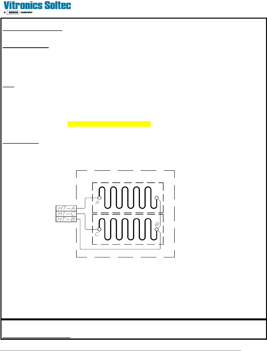
The diagram below represents a heater assembly within a Cell.
If the heater assembly does not resistance check close to the listed values, (or, if any measurement shows “open”), the
heater assembly must be replaced. Resistance values vary slightly between heaters in Air and Nitrogen Ovens.
To replace a heater assembly, refer to “Heater Remove / Replace Procedures”.
EXCESSIVE EXHAUST FLOW
13