Technical_reference - 第35页
Technical Service Manual 35 Revision Dat e: August 2004 RA DICAL RECIPE CHA NGE SYMPTOMS 1 through 6 For all of the following symptom s: 1. Tem peratur e =< 10 degrees above setpoint and s table 2. Tem perature s low …
Technical Service Manual 34 Revision Date: August 2004
GROUNDING PROBLEMS
The oven is indicating what appear to be random high temperatures due to a grounding problem.
POSSIBLE CAUSES
Each T/C is grounded at the controller when it is properly connected. If there is a poor connection to ground at this point,
the T/C reading will be unreliable and will indicate random high temperatures.
Check the ground connection AT THE CONTROLLER. Make sure that it is correct.
Use an Ohmmeter to check the connections and refer to the oven prints to make sure that the connections are correct.
(The grounding problem is usually electrical noise on the ground or a faulty facility ground with high resistance. This can
result in the noise affecting the T/C reliability.
(FOR FUTURE USE)
EXTERNAL AIR FORCED INTO HEAT TUNNEL
The oven is exhibiting random low temperatures due to external air entering the oven tunnel.
POSSIBLE CAUSES
ICBs (inter cell baffles): If the ICBs are improperly adjusted, it allows air from outside to enter the oven tunnel, resulting in
random low temperatures (Refer to the chart of initial slot settings for the oven.)
EXTERNAL DISTURBANCES: The reflow process is also susceptible to external cold air and large airflow events outside
the oven. For instance, locating the oven next to a large loading dock area could cause this problem. The XPM Series
ovens are not very susceptible to external influences, but under the right circumstances, this is a possibility.
AIR LEAKS: Check for air leaks in the oven tunnel.
(External air forced into the Oven tunnel usually affects only the first 1 or 2 zones)
28
29
30
Technical Service Manual 35 Revision Date: August 2004
RADICAL RECIPE CHANGE
SYMPTOMS 1 through 6
For all of the following symptoms:
1. Temperature =< 10 degrees above setpoint and stable
2. Temperature slow rise past set point
3. Temperature rapid rise past set point
4. Temperature rises but doesn’t reach set point
5. Temperature appears to stay cold
6. Temperature drops from set point
POSSIBLE CAUSES
A radical change in the running recipe can cause these symptoms. An example of a radical change would be switching
from a reflow recipe to a curing recipe or vice versa. If you are experiencing this problem and cannot work around it, call
the Vitronics-Soltec Field Service or Applications Support departments for assistance.
(FOR FUTURE USE)
31
32
Technical Service Manual 36 Revision Date: August 2004
HEATER TESTING PROCEDURE
When a heating problem is suspected, applying this procedure should reduce the time required to eliminate a number of
items that may NOT be responsible for the problem. This will leave a much smaller number of possibilities for
consideration.
To be effective and efficient, the trouble-shooting process does not jump directly to the “answer”, but rather, eliminates all
of the possibilities one-at-time with a systematic approach, until only the “answer” remains.
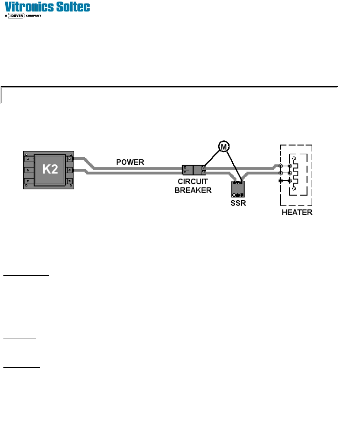
SIMPLIFIED HEATER CONTROL CIRCUIT
EXPLANATION:
Each heater has a Circuit Breaker and SSR. K2 supplies two hot, high voltage conductors to the Line Side of the Heater
Circuit Breaker(s). Both of the current paths are interrupted by the Circuit Breaker when it is open or tripped.
A) On the Load Side of the Circuit Breaker, one of the conductors goes directly to the heater terminals (HT-A,
HT-B, HT-C) on the outside of the Heater Cell.
B) The other conductor is interrupted by the SSR. When the SSR operates, it conducts power from the Circuit
Breaker to the heater terminals (1, 1A, and 2) on top of the Heater Cell.
O.K. TEST: Check the heater(s) for agreement with the “HEATER RESISTANCE REFERENCE CHART” after
disconnecting the supply conductors at the heater terminals
(HT-A, HT-B, HT-C) on top of the Heater Cell. (This does work, however, it is time consuming, and does not check the
conductors between the Circuit Breaker / SSR and the Heater Cell.)
BEST TEST: The heater(s) and conductors can be checked at the Circuit Breakers/SSRs. Reference the “ HEATER
RESISTANCE CHECK LOCATIONS” diagram.