Technical_reference - 第36页
Technical Service Manual 36 Revision Dat e: August 2004 HEATER T ESTING PROCEDURE W hen a heating problem is suspec ted, apply ing this procedur e should reduc e the time r equired to elim inate a num ber of items that m…
Technical Service Manual 35 Revision Date: August 2004
RADICAL RECIPE CHANGE
SYMPTOMS 1 through 6
For all of the following symptoms:
1. Temperature =< 10 degrees above setpoint and stable
2. Temperature slow rise past set point
3. Temperature rapid rise past set point
4. Temperature rises but doesn’t reach set point
5. Temperature appears to stay cold
6. Temperature drops from set point
POSSIBLE CAUSES
A radical change in the running recipe can cause these symptoms. An example of a radical change would be switching
from a reflow recipe to a curing recipe or vice versa. If you are experiencing this problem and cannot work around it, call
the Vitronics-Soltec Field Service or Applications Support departments for assistance.
(FOR FUTURE USE)
31
32
Technical Service Manual 36 Revision Date: August 2004
HEATER TESTING PROCEDURE
When a heating problem is suspected, applying this procedure should reduce the time required to eliminate a number of
items that may NOT be responsible for the problem. This will leave a much smaller number of possibilities for
consideration.
To be effective and efficient, the trouble-shooting process does not jump directly to the “answer”, but rather, eliminates all
of the possibilities one-at-time with a systematic approach, until only the “answer” remains.
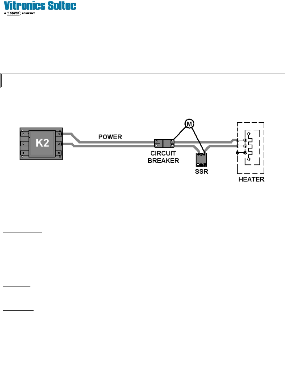
SIMPLIFIED HEATER CONTROL CIRCUIT
EXPLANATION:
Each heater has a Circuit Breaker and SSR. K2 supplies two hot, high voltage conductors to the Line Side of the Heater
Circuit Breaker(s). Both of the current paths are interrupted by the Circuit Breaker when it is open or tripped.
A) On the Load Side of the Circuit Breaker, one of the conductors goes directly to the heater terminals (HT-A,
HT-B, HT-C) on the outside of the Heater Cell.
B) The other conductor is interrupted by the SSR. When the SSR operates, it conducts power from the Circuit
Breaker to the heater terminals (1, 1A, and 2) on top of the Heater Cell.
O.K. TEST: Check the heater(s) for agreement with the “HEATER RESISTANCE REFERENCE CHART” after
disconnecting the supply conductors at the heater terminals
(HT-A, HT-B, HT-C) on top of the Heater Cell. (This does work, however, it is time consuming, and does not check the
conductors between the Circuit Breaker / SSR and the Heater Cell.)
BEST TEST: The heater(s) and conductors can be checked at the Circuit Breakers/SSRs. Reference the “ HEATER
RESISTANCE CHECK LOCATIONS” diagram.

Technical Service Manual 37 Revision Date: August 2004
PROCEDURE:
1) Disconnect ALL POWER to the Oven.
2) Check for Tripped Heater Circuit Breakers, (F8 & F11 are not heater circuit breakers) If a circuit breaker is tripped
(open), (See 10, and 17 in the Heating System Diagnostic tree)
3) Open ALL Heater Circuit Breakers: F1-B to F12-B and F1-T to F12-T (Depending on Oven size, the highest CB No.
may not be 12 as shown in the illustration on the next page)
4) Perform Resistance Checks. See “HEATER RESISTANCE REFERENCE CHART” (Oven Type & Voltage must be
known) See “ HEATER RESISTANCE CHECK LOCATIONS” and connect Meter (M) on CBs and SSRs as shown.
A) If the resistance is “infinite” (open), the Heater may have a broken/disconnected wire or the heater element
may have an “open” in it.
B) If the resistance on Parallel wired Heaters - (see “CHART”, Fig A)- is twice what it should be:
1. One Heater element may be “open”
2. One conductor from the Heater may be disconnected.
3. The jumper from term (1) to term (1A) may be missing or loose.
C) If the resistance is in agreement with the “HEATER RESISTANCE REFERENCE CHART”, then it is
reasonable to expect that the Heater and its conductors are in proper operating condition.
5) Close ALL Heater Circuit Breakers.
6) Refer to “HEATING - Problems and Possible Solutions” for other possibilities.