Technical_reference - 第39页
Technical Service Manual 39 Revision Dat e: August 2004 Fig. A Fig. B (Paral lel ) (Serie s) XPM 2 Release Date: February 25, 2004 Heater Element R esistance Reference Chart VOLT A GE RESIST A NCE HOLE SIZE HEA TER ASSY …
Technical Service Manual 38 Revision Date: August 2004
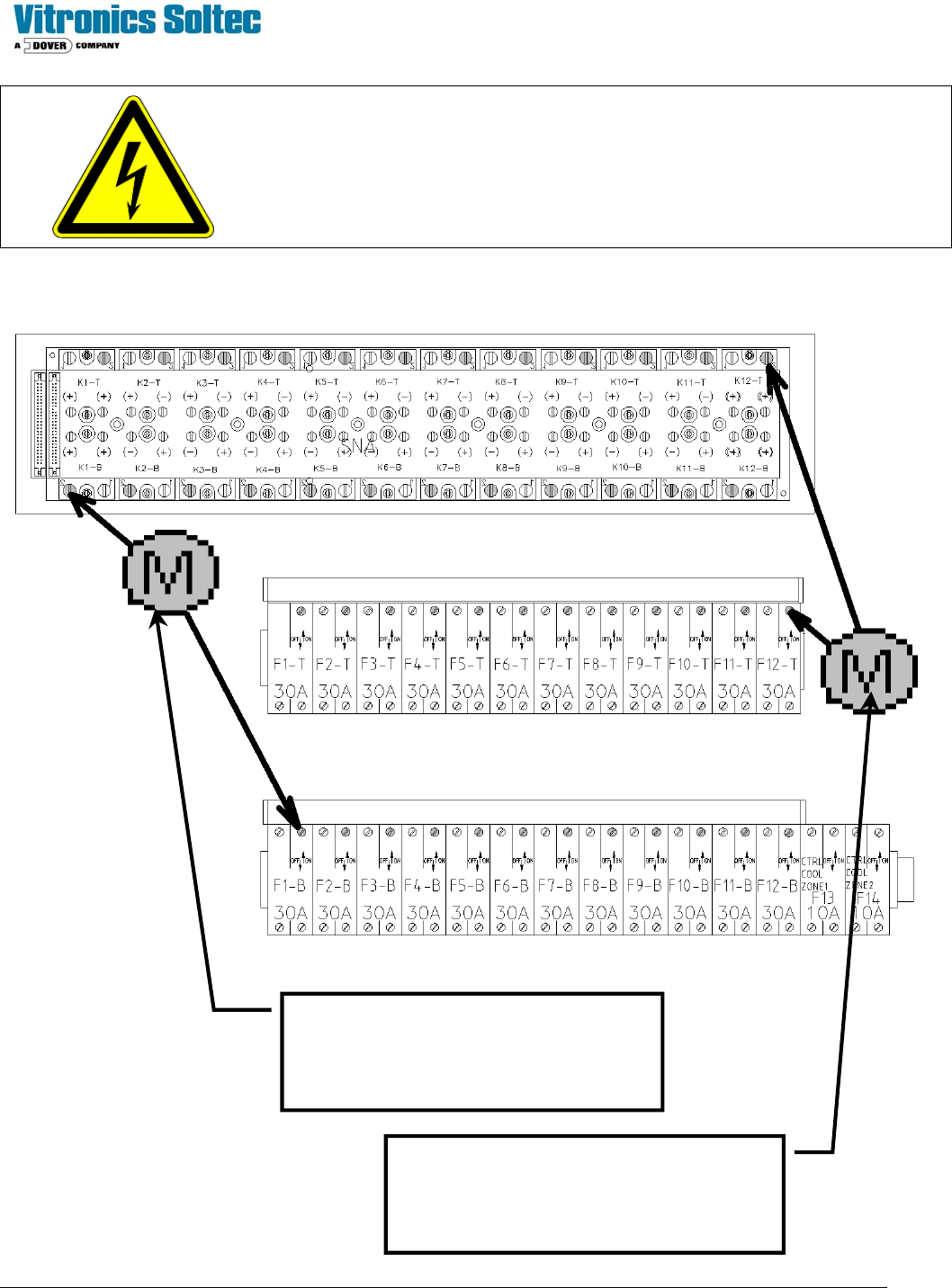
CAUTION:
DISCONNECT ALL POWER BEFORE TESTING
Heater Resistance Check Locations
Read resistance with Ohmmeter across
these two terminals to check the heater
resistance for Heater No. 1-B.
(Heaters 2B thru 12B are similar)
Read resistance with Ohmmeter across these
two terminals to check the heater resistance
for Heater No. 12-T.
(Heaters 2T thru 12T are similar)
Top Heater Circuit Breakers
Bottom Heater Circuit Breakers
Technical Service Manual 39 Revision Date: August 2004
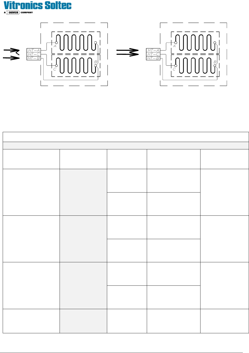
Fig. A Fig. B
(Parallel) (Series)
XPM
2
Release Date: February 25, 2004
Heater Element Resistance Reference Chart
VOLTAGE RESISTANCE HOLE SIZE HEATER ASSY #
(
stamped on face plate)
ELEMENT #
(2 ELEMENTS PER
HEATER)
.136”
3085401
200 - 208 Volts
(LOW RANGE)
Test: 8.55 Ω - 9.45 Ω
9.0 Ω nominal
18.0 Ω = 1 open element
.170”
3160501
0866601
.136”
3085401
380 - 415 Volts
(LOW RANGE)
Test: 34.20 Ω - 37.80 Ω
36.0 Ω nominal
.170”
3160501
0866601
.136”
3085402
220 - 240 Volts
(HIGH RANGE)
Test: 11.40 Ω - 12.60Ω
12.0 Ω nominal
24.0 Ω = 1 open element
.170”
3160502
0904001
440 – 480 Volts
(HIGH RANGE)
Test: 45.60 Ω - 50.40 Ω
48.0 Ω nominal
.136”
3085402
0904001

Technical Service Manual 40 Revision Date: August 2004
TEST PROCEDURE FOR HEATER GROUND CONTINUITY
1) Disconnect the main power connection to the oven and disable all heater circuit breakers.
2) Check each line to the respective heater element for a short to ground using an Ohmmeter.
3) The heater element conductors should be completely isolated from ground (i.e. open circuit with reference to ground).
MAXIMUM HEATERS ON
The Oven Control Program limits the maximum number of heaters to be energized at the same time to seven.
MAXIMUM PHASE IMBALANCE
The difference between the maximum loaded phase and the minimum loaded phase is limited to two heaters by the Oven
Control Program. The Oven Control Program limits the number of heaters “ON” at the same time for each phase.
THERMOCOUPLES
All thermocouples in the oven are type 'K', and identified by a red (-) and a yellow (+) wire. Connectors, wires and
terminals must be designated for use with type “K” thermocouples.
TEST PROCEDURE
1) Remove the thermocouple connection block from the front of the AI board in the Oven controller.
2) Measure the resistance of each thermocouple using an Ohmmeter. (All T/Cs have one side connected to ground.For
best results, isolate the T/C being tested)
3) The resistance of a thermocouple wire should be approximately 5 ohms.
4) Test for shorts between the thermocouple wires by disconnecting the thermocouple cable from the plug on the
outside of the cell.
5) Measure the resistance between the two thermocouple wires; it should be open circuit with the connector removed
from the front of the controller.
6) Check for short circuit to ground on both thermocouple wires.
7) Wiring connections must be tight. Verify that all negative thermocouple connections are grounded, along with all
unused thermocouple ports on the front of the controller.
8) Check to determine that one side of the TC probe is NOT common to ground.